Op-Amps and Voltage Comparators
An operational amplifier is fundamentally a differential amplifier with extremely high gain. It relies on an external feedback network to achieve precise, controllable voltage amplification. In real projects, its main job is to take weak analog signals from sensors, amplify them, filter them, condition them, and turn them into something the MCU can reliably read.
Core Characteristics
- Virtual open: op-amp inputs have extremely high impedance (1MΩ+), drawing virtually no current. Think of them as probes that touch the signal line without altering it. In analysis, just treat both inputs as open circuits. This is called the virtual open — short for “false open circuit.”
- Virtual short: with negative feedback present, the op-amp fights hard to force the inverting input (-) voltage to match the non-inverting input (+). Every gain calculation traces back to this. When I first truly understood this, a whole bunch of circuits suddenly clicked.
Other Characteristics
- Output saturation — the output can’t exceed the supply rails: op-amp output is always bounded by the power rails, usually slightly below them. If the theoretical amplified value exceeds the supply, the output clips and you’re no longer linear.
- Voltage follower is the special case where Rf=0, Rg=∞, giving gain = 1. It doesn’t amplify voltage — instead it transforms a weak, high-impedance sensor signal into a strong, low-impedance drive signal, buffering one stage from the next.
Non-Inverting Amplifier
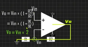
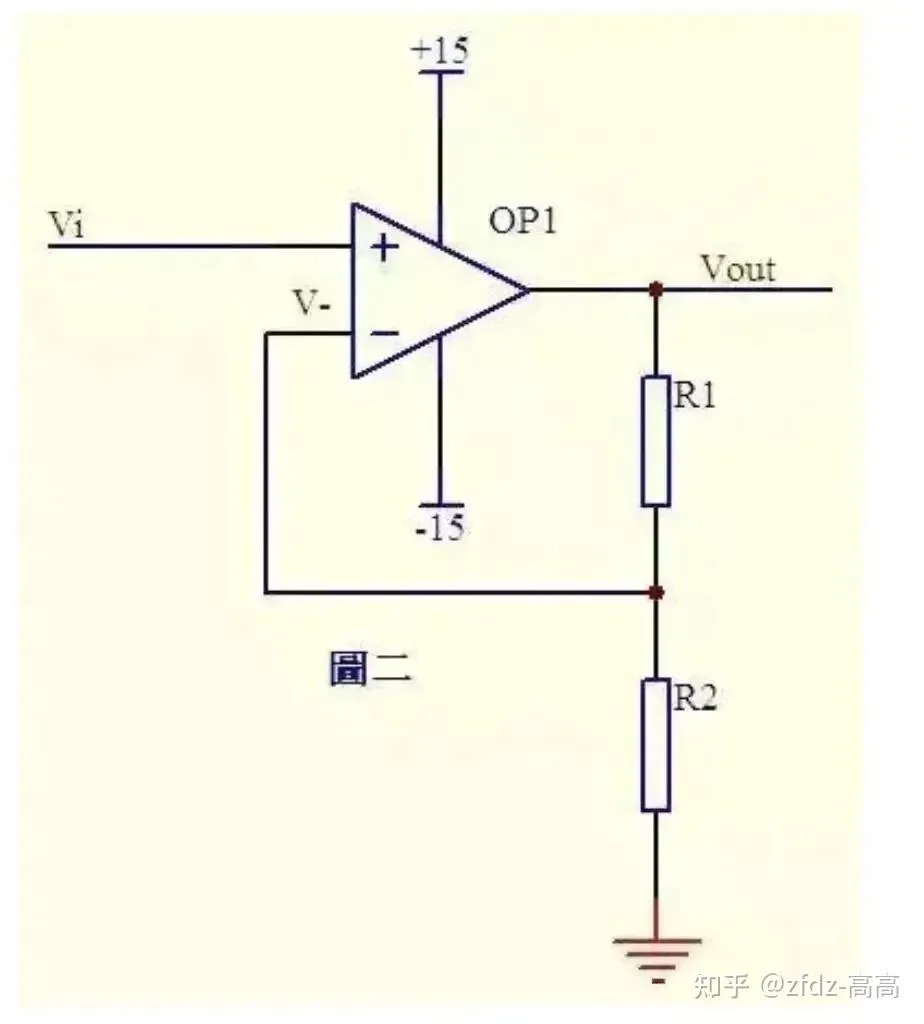
Signal enters at the (+) input. Feedback resistor Rf (R2) connects output to (-), and Rg (R1) goes from (-) to ground. The output actively rises until the voltage divider formed by Rf and Rg matches the input voltage.
Formula: Vout = Vin × (1 + Rf/Rg)
Derivation: Vi and V- are virtually shorted, so Vi = V- …(a) Due to virtual open, no current flows into the inverting input. Current through R1 and R2 is equal — call it I: I = Vout / (R1 + R2) …(b) Vi equals the voltage across R2: Vi = I × R2 …(c) From (a), (b), (c): Vout = Vi × (R1 + R2) / R2
Inverting Amplifier
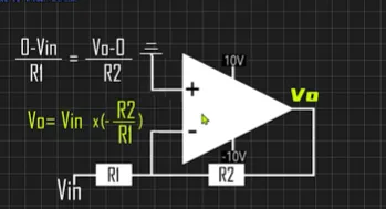
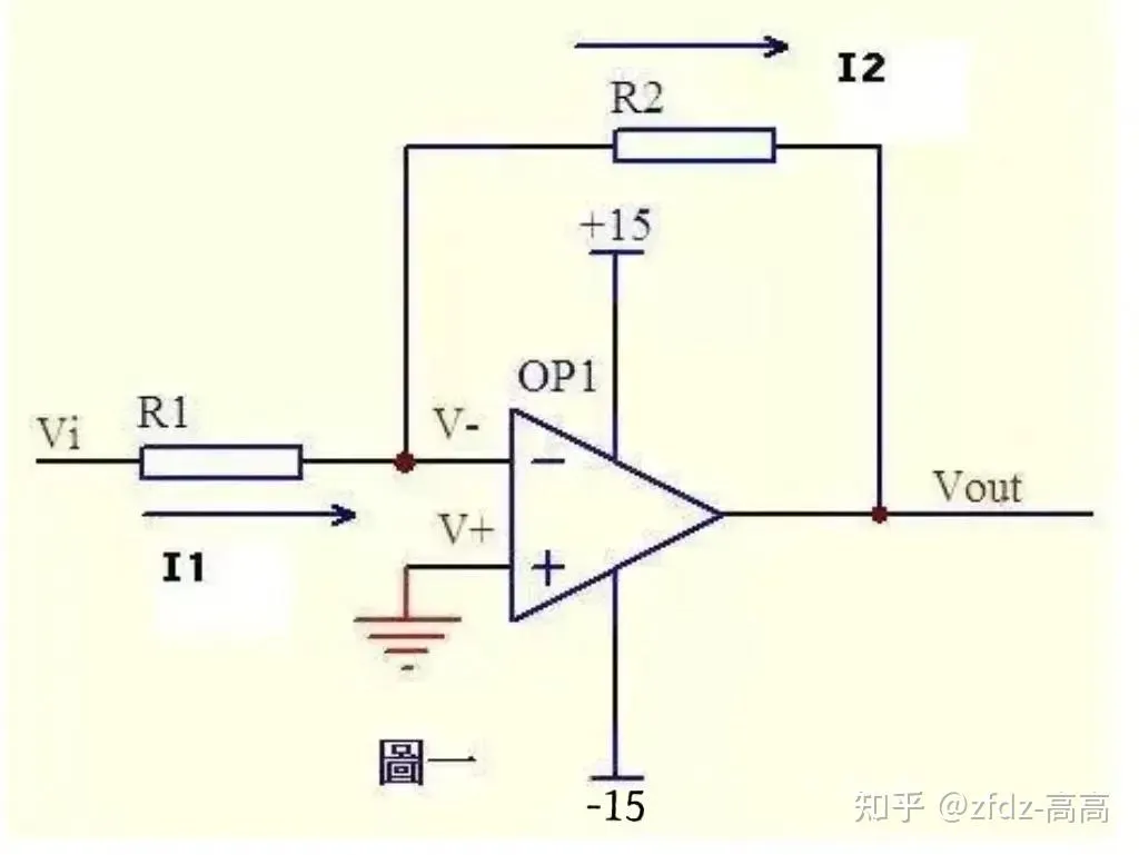
Signal enters at the inverting input (-); the non-inverting input (+) is grounded. Output is 180° out of phase with the input: input goes up, output goes down.
Formula: Vout = (-R2/R1) × Vi
Derivation: The non-inverting input is grounded = 0V. Virtual short forces the inverting input to 0V as well. Virtual open means almost no current enters or leaves the op-amp inputs, so R1 and R2 are effectively in series with the same current through both.
Current through R1: I1 = (Vi - V-) / R1 …(a) Current through R2: I2 = (V- - Vout) / R2 …(b) V- = V+ = 0 …(c) I1 = I2 …(d)
Solving together: Vout = (-R2/R1) × Vi
Non-Inverting vs Inverting
| Property | Non-Inverting | Inverting |
|---|---|---|
| Input impedance | Extremely high (MΩ) | Equals Rin (kΩ) |
| Gain | 1+Rf/Rg, ≥1 | −Rf/Rin, can be <1 |
| Output phase | Same as input | Inverted |
| Virtual ground | No | Yes, at inverting input |
| Typical use | High-Z buffer, sensors | Audio mix, inversion, I-V |
Virtual ground is particularly important in the inverting configuration. Because the (+) input is tied to real ground, virtual short pulls the (-) input to ~0V too — but this 0V isn’t a real ground connection. The op-amp output actively maintains it through the feedback resistor. The input impedance the signal source sees is just Rin itself, usually a few kΩ to tens of kΩ — completely different from the near-infinite impedance of the non-inverting configuration. The inverting input hangs at an invisible zero point.
Non-Inverting Amp in Real Products
- Electronic scales / pressure sensors: bridge sensor’s weak differential signal gets amplified through an instrumentation amp (or three-op-amp structure), then fed to ADC. Range design must avoid clipping.
- Temperature controllers: thermocouple microvolt signals get amplified, then one path goes to the display, another to a comparator against a set threshold, driving a relay.
- PIR infrared motion sensors: the PIR outputs a tiny AC signal, amplified through an op-amp bandpass filter, then detected by a comparator to trigger lighting.
- Motor current sensing: millivolt drop across a shunt resistor gets amplified and sent to the MCU for overcurrent protection.
- Audio products: electret microphone signal gets AC-amplified and filtered, then fed to a power amp or ADC.
Inverting Amp in Real Products
- Audio mixers: multiple audio channels each go through their own Rin, all summed at the inverting op-amp’s virtual ground point. Channels don’t interfere with each other. This is the classic “adder” application.
- Sensor signal inversion: some sensors output in the opposite direction from the physical quantity (e.g., pressure up → voltage down). One inverting stage flips it right-side-up before the MCU.
- Current-to-voltage conversion: remove Rin entirely, feed the sensor current directly into the inverting input, use Rf to linearly convert current to voltage. Photodiode detection circuits almost always do this.
- Differential amplifier building block: combine inverting and non-inverting stages to extract weak differential signals from noisy common-mode environments. Industrial sensor front-ends use this heavily.
Design Notes — Things I’ve Learned
- Supply rail headroom: standard op-amps (like LM358) can’t swing all the way to the rails. On 5V supply, max output ≈ VCC-1.5V = 3.5V. If your MCU’s ADC reference is 3.3V, that lines up nicely. If you need rail-to-rail swing, get a rail-to-rail op-amp.
- Input common-mode range: LM358 inputs go down to ground but only up to VCC-1.5V. If your input is 6V on a 5V supply, you’re outside the common-mode range and the op-amp misbehaves.
- Gain-bandwidth product: LM358 is only ~1MHz. Fine for thermal, optical, and slow signals — not for high-frequency stuff.
- Bias current path: the inverting input needs a DC path to ground through a resistor. The input bias current has to go somewhere — without a path, “virtual open” breaks down and the output drifts.
- Decoupling: 0.1μF cap at the op-amp supply pins to ground. Never skip this.
- Comparator hysteresis: when the input hovers near the threshold, a bare comparator oscillates wildly. Add positive feedback (large resistor from output to (+) input) to create a hysteresis window. Clean switching. Mandatory for any production circuit.
A comparator is fundamentally different from an op-amp: it doesn’t pursue linearity — it makes instant binary decisions. V+ > V- → output HIGH (or pulled HIGH by external resistor), V+ < V- → output LOW. Only two results: yes or no.
Classic Circuits — Derived By Hand
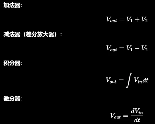
Adder 1
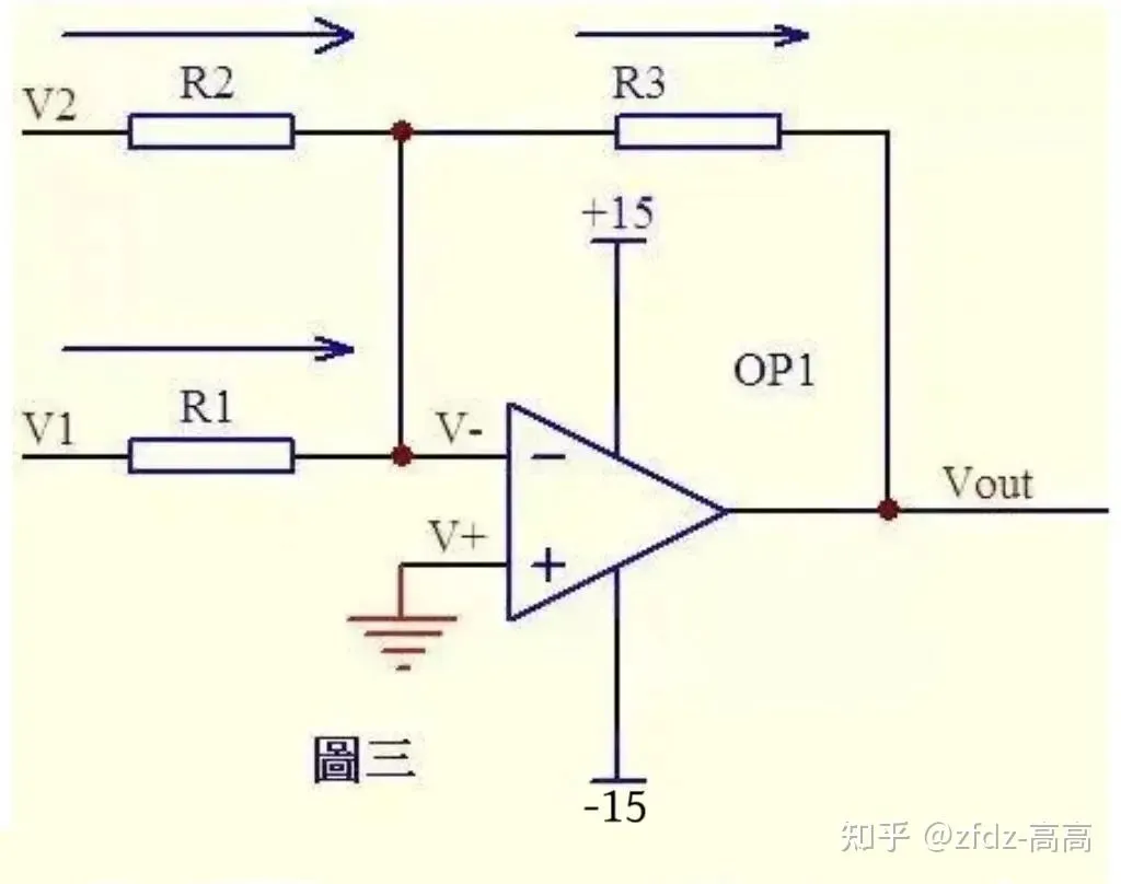
From virtual short: V- = V+ = 0 …(a) From virtual open and Kirchhoff’s law, the sum of currents through R2 and R1 equals the current through R3: (V1 - V-) / R1 + (V2 - V-) / R2 = (V- - Vout) / R3 …(b) Substituting (a): V1/R1 + V2/R2 = -Vout/R3 If R1 = R2 = R3, then: -Vout = V1 + V2
Adder 2
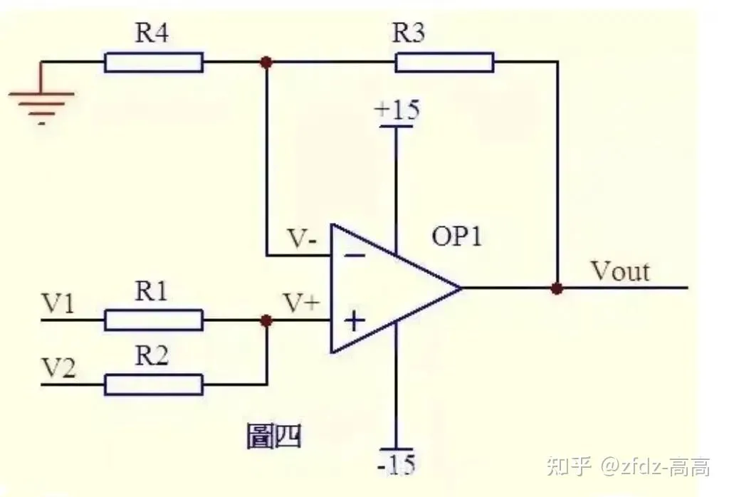
Due to virtual open, no current flows into the non-inverting input. Current through R1 equals current through R2. Similarly, current through R4 equals current through R3: (V1 - V+) / R1 = (V+ - V2) / R2 …(a) (Vout - V-) / R3 = V- / R4 …(b) From virtual short: V+ = V- …(c) If R1 = R2 and R3 = R4, deriving from above: V+ = (V1 + V2) / 2, V- = Vout / 2 Therefore: Vout = V1 + V2
Subtractor
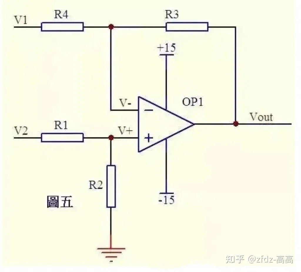
From virtual open, current through R1 equals current through R2. Similarly, current through R4 equals current through R3: (V2 - V+) / R1 = V+ / R2 …(a) (V1 - V-) / R4 = (V- - Vout) / R3 …(b) If R1 = R2: V+ = V2 / 2 …(c) If R3 = R4: V- = (Vout + V1) / 2 …(d) From virtual short: V+ = V- …(e) So: Vout = V2 - V1 — the classic subtractor.
Integrator
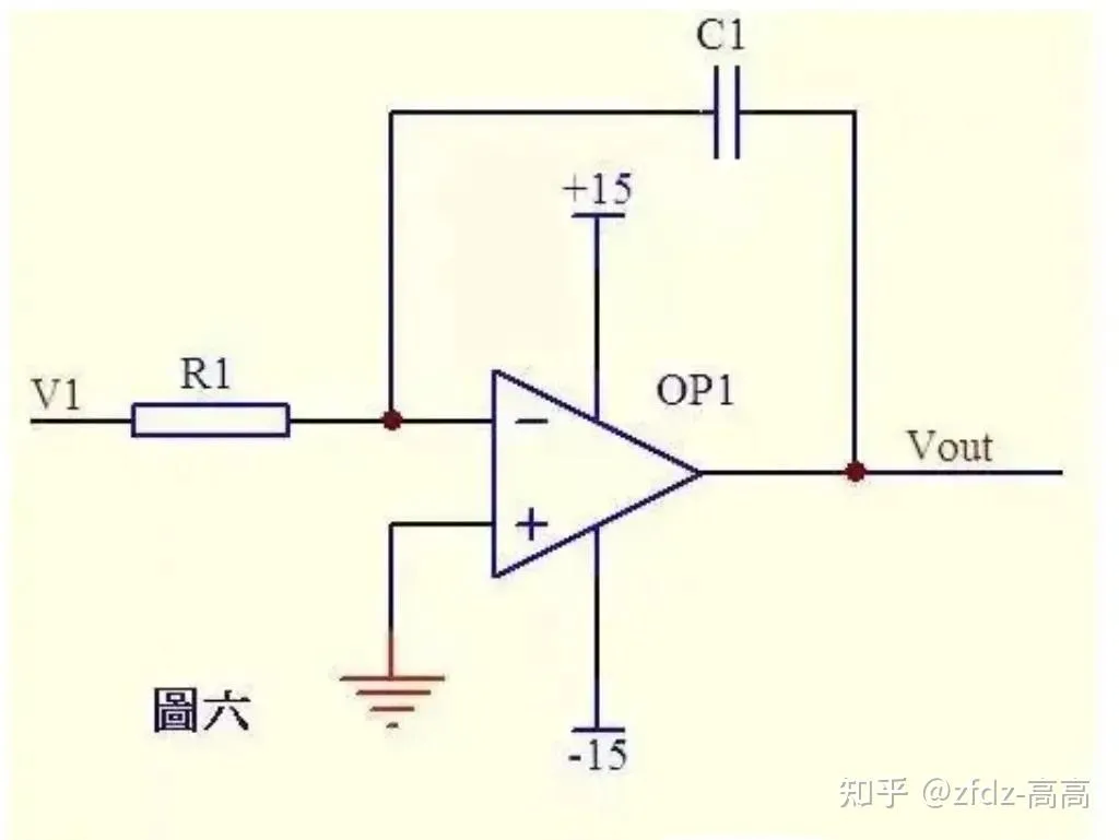
From virtual short, the inverting input voltage equals the non-inverting input. From virtual open, current through R1 equals current through C1.
Current through R1: i = V1 / R1 Current through C1: i = C × dUc/dt = -C × dVout/dt Therefore: Vout = (-1/(R1 × C1)) ∫ V1 dt
Output voltage is proportional to the integral of the input voltage over time. If V1 is a constant voltage U: Vout = -U × t / (R1 × C1)
t is time, and Vout is a straight line ramping linearly from 0 toward the negative supply.
Differentiator
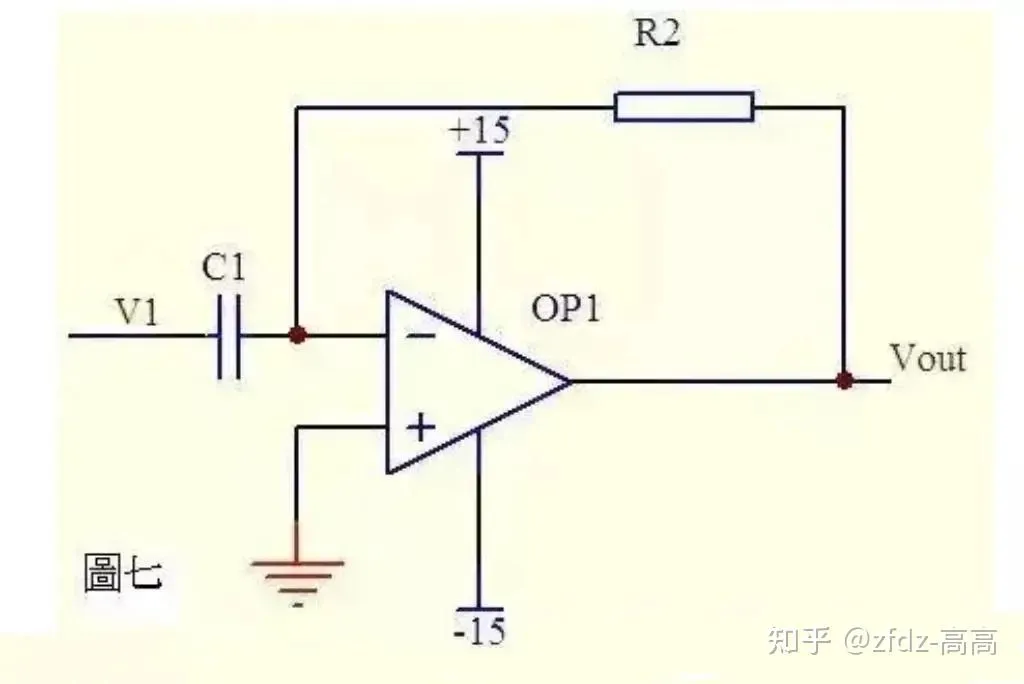
From virtual open, current through capacitor C1 and resistor R2 is equal. From virtual short, the op-amp inputs are at equal voltage: Vout = -i × R2 = -(R2 × C1) dV1/dt
If V1 is a suddenly applied DC voltage, Vout produces a sharp pulse in the opposite direction.
Differential Amplifier
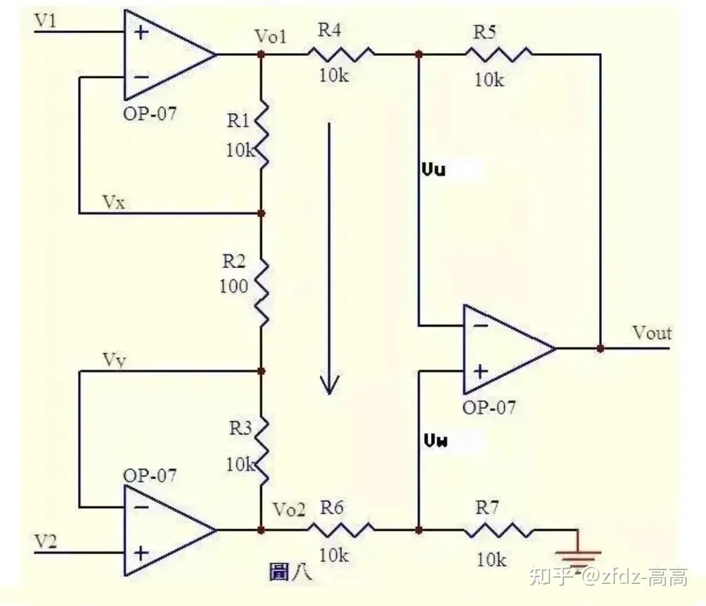
From virtual short: Vx = V1 …(a), Vy = V2 …(b) From virtual open, no current flows into op-amp inputs. R1, R2, R3 are effectively in series with the same current through each: I = (Vx - Vy) / R2 …(c) So: Vo1 - Vo2 = I × (R1 + R2 + R3) = (Vx - Vy)(R1 + R2 + R3) / R2 …(d)
From virtual open, current through R6 equals current through R7. If R6 = R7: Vw = Vo2 / 2 …(e) Similarly, if R4 = R5: Vout - Vu = Vu - Vo1, so: Vu = (Vout + Vo1) / 2 …(f) From virtual short: Vu = Vw …(g) From (e), (f), (g): Vout = Vo2 - Vo1 …(h) From (d), (h): Vout = (Vy - Vx)(R1 + R2 + R3) / R2
The term (R1+R2+R3)/R2 is a constant that sets the amplification factor for the difference (Vy - Vx). This is the differential amplifier.
Current Detection (4-20mA)
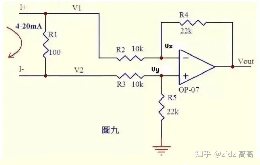
Many controllers accept 020mA or 420mA current from instrumentation. The circuit converts this current to a voltage for the ADC.
The 420mA current flows through a 100Ω sense resistor R1, producing a 0.42V voltage drop across it.
From virtual open, no current flows into op-amp inputs. Current through R3 equals current through R5, and current through R2 equals current through R4:
(V2 - Vy) / R3 = Vy / R5 …(a)
(V1 - Vx) / R2 = (Vx - Vout) / R4 …(b)
From virtual short: Vx = Vy …(c)
As current varies from 020mA: V1 = V2 + (0.42) …(d)
Substituting (c), (d) into (b): (V2 + (0.42) - Vy) / R2 = (Vy - Vout) / R4 …(e)
If R3 = R2 and R4 = R5, then (e) - (a) gives: Vout = -(0.42)R4/R2 …(f)
Here R4/R2 = 22k/10k = 2.2, so: Vout = -(0.88~4.4)V
In other words, 420mA is converted to -0.88-4.4V, ready for the ADC. Reverse the current direction and Vout = +(0.88~4.4)V.
Voltage-to-Current Converter
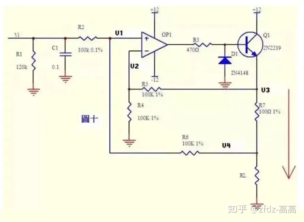
Current can be converted to voltage, and voltage can be converted to current. This circuit’s negative feedback doesn’t go through a resistor directly — it passes through transistor Q1’s emitter junction. Don’t mistake this for a comparator — as long as we’re in the active region, virtual short and virtual open still apply.
From virtual open: (Vi - V1) / R2 = (V1 - V4) / R6 …(a) Similarly: (V3 - V2) / R5 = V2 / R4 …(b) From virtual short: V1 = V2 …(c) If R2 = R6 and R4 = R5, from (a), (b), (c): V3 - V4 = Vi
This means the voltage across R7 equals the input voltage Vi, so current through R7: I = Vi / R7 If RL << 100kΩ, the current through RL is essentially the same as through R7.
PT100 Sensor Front-End
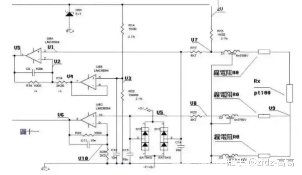
A 3-wire PT100 preamplifier circuit. The PT100 sensor uses three wires of identical material, gauge, and length. 2V is applied across the bridge formed by R14, R20, R15, Z1, PT100, and its lead resistances. Z1, Z2, Z3, D11, D12, D83, and the capacitors provide filtering and protection — treat them as shorts (Z1/Z2/Z3) or opens (D11/D12/D83 and caps) for static analysis.
From the resistor divider: V3 = 2 × R20 / (R14 + 20) = 200/1100 = 2/11 …(a) From virtual short, U8B pins 6, 7 voltage equals pin 5 voltage: V4 = V3 …(b) From virtual open, U8A pin 2 draws no current. Current through R18 equals current through R19: (V2 - V4) / R19 = (V5 - V2) / R18 …(c) From virtual open, U8A pin 3 draws no current: V1 = V7 …(d)
In the bridge, R15 and Z1 are in series with PT100 and lead resistances. The voltage across PT100 + lead resistances feeds through R17 to U8A pin 3: V7 = 2 × (Rx + 2R0) / (R15 + Rx + 2R0) …(e) From virtual short: V1 = V2 …(f) From (a) through (f): (V5 - V7) / 100 = (V7 - V3) / 2.2 Simplifying: V5 = (102.2 × V7 - 100V3) / 2.2 i.e.: V5 = 204.4(Rx + 2R0) / (1000 + Rx + 2R0) - 200/11 …(g)
Now for lead resistance. The voltage drop across the bottom lead resistance feeds through the middle lead wire, Z2, and R22 to U8C pin 10.
From virtual open: V5 = V8 = V9 = 2 × R0 / (R15 + Rx + 2R0) …(a’) (V6 - V10) / R25 = V10 / R26 …(b’) From virtual short: V10 = V5 …(c’) From (a’), (b’), (c’): V6 = (102.2/2.2)V5 = 204.4R0 / [2.2(1000 + Rx + 2R0)] …(h)
From the system of equations (g) and (h), measuring V5 and V6 lets you solve for Rx and R0. Knowing Rx, look up the PT100 table to get the temperature.
Where the Name Comes From
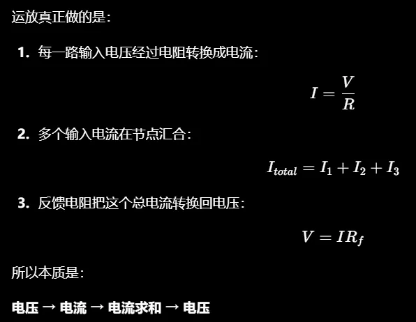
“Operational amplifier” comes from the early analog computer era: these circuits literally performed mathematical operations.
Summary — Op-Amp vs Comparator
Op-amps (like LM358) operate in the linear region. With negative feedback, they fight to keep both inputs equal (virtual short holds), and the output is a continuously varying analog voltage proportional to the input. They’re built for amplification — precision, fidelity, low distortion. Taking a 0.2V photodiode signal to 2V with the waveform intact — that’s an op-amp’s job. You can temporarily use an op-amp open-loop as a comparator, but it’s not what they’re designed for.
Comparators (like LM393) operate in saturation / open-loop. They deliberately let the two inputs diverge, and the output slams to a rail (HIGH or LOW) — only two states. They’re built for decision-making — speed, clean switching, unambiguous logic levels. Setting a 2.5V threshold and lighting an LED when crossed — that’s a comparator’s job.
My rule of thumb:
- Need to read a continuous analog value (temperature curve, light level, pressure waveform) → use an op-amp for buffering, amplification, and filtering, then feed the ADC.
- Need to make a binary decision (temp threshold reached, motion detected, battery low) → use a comparator for a clean HIGH/LOW output or interrupt trigger.