Power Supply Design — Three Questions I Ask First
Before touching any other part of the schematic, I ask myself three questions:
- What’s the input-output voltage difference? If it’s over 3V and current exceeds 0.3A, I don’t even consider an LDO — straight to Buck.
- Is the system noise-sensitive? Wireless modules and precision analog circuits lean toward LDOs, or at least extra filtering after a switcher.
- What’s the space and thermal situation? A fully sealed tiny enclosure means I’m going switching — heat builds up fast in a small box.
These three questions have saved me a lot of rework.
Power Architecture — It’s an Energy Distribution System
After a while I realized: power design isn’t about “generating electricity.” It’s about getting the right voltage, the right current, and the right noise level to each module, exactly where it’s needed. When I look at any PCB now, my first instinct is to find the power entry and trace the power path downstream.
1. Power Systems Are Multi-Stage Conversion Chains
A typical product power chain looks like this:
Input (USB/Battery) → Protection (fuse, reverse-polarity) → Charge management → Battery → DC/DC conversion → Multiple voltage rails → MCU/Sensors/LEDs/MotorsDifferent blocks on the same board need different voltages:
| Module | Typical Voltage |
|---|---|
| MCU | 3.3V |
| Arduino | 5V |
| Sensors | 1.8~3.3V |
| LEDs | 2~3V |
| High-power loads | 12V/24V |
So inside a product you often have 5V, 3.3V, 1.8V, and other rails coexisting.
What I’ve learned:
- Every stage in the power path has losses — evaluate efficiency stage by stage, not just the last one.
- Plan your voltage rails thoughtfully. Sensitive circuits may need extra filtering on their supply.
- Protection devices (fuse, reverse-polarity) look basic but define your product’s safety floor. Never cheap out here.
2. LDO Linear Regulators — Clean and Simple, But They Get Hot
An LDO essentially burns excess voltage as heat. The math is clear:
P_loss = (Vin - Vout) × IBut LDOs aren’t always inefficient — it depends on the scenario. Small voltage drop: 5.5V to 5V at 1A, P_loss = 0.5W, ~91% efficient — totally fine. Large drop: 12V to 5V at 1A, P_loss = 7W, only 42% efficient — terrible.
LDO advantages: dead simple circuit (input cap + LDO + output cap, that’s it), low cost, low noise, stable output.
I reach for an LDO when:
- Dropping 3.6V Li-ion to 3.3V for an MCU or sensor — only 0.3V dropout, barely any heat.
- Feeding noise-sensitive analog/RF circuits (audio amps, ADC references).
- I would NOT use one for 12V-to-5V at high power — you’d need a massive heatsink. Not worth it.
Practical lessons:
- After calculating P_loss, junction temp = ambient + P_loss × θJA. Keep it in the safe zone.
- Big voltage drop + high current? Use a switcher. Don’t force an LDO.
- PCB copper can serve as a heatsink — pour copper under the LDO tab, stitch with vias. Effectively lowers thermal resistance.
3. Buck Switching Converters — Efficient, But With Ripple
A Buck takes a completely different approach: instead of burning excess voltage, it switches a MOSFET on and off at high speed and smooths the output with an LC filter. Efficiency is typically 85%–97%.
The trade-off: output has high-frequency ripple, and you need more external components — at minimum an inductor, a freewheeling diode (or synchronous rectifier MOSFET), and input/output caps.
I default to Buck when the voltage drop exceeds ~3V and current is above ~0.3A — like 12V systems, or stepping battery voltage down for high-power loads. The LM2596 module is my prototyping staple — adjustable output, cheap, reliable.
Lessons learned the hard way:
- Inductor selection is critical: saturation current must exceed max load current. Once an inductor saturates, it’s basically a wire — and your MOSFET dies instantly.
- Keep the switching node trace short and wide to minimize EMI.
- For sensitive circuits, add an LDO or π filter after the Buck to suppress ripple.
4. Boost and Buck-Boost
- Boost: Steps voltage up. Single Li-ion cell 3.7V → 5V or 12V. Principle: switch ON stores energy in the inductor; switch OFF releases it in series with the input, making Vout > Vin.
- Buck-Boost: Handles the case where Vin might be above or below Vout. A Li-ion battery ranges from 4.2V full to 2.7V near empty, but you need steady 3.3V — Buck-Boost automatically switches between modes.
Practical notes:
- Boost circuits can have inrush current at startup — soft-start is basically standard.
- Buck-Boost efficiency is typically a few points lower than pure Buck or Boost due to extra switching.
- Boost output can’t be directly shorted — plan your protection ahead of time.
5. Battery Charging and Protection — Both Are Mandatory
You absolutely cannot charge a Li-ion cell by connecting 5V directly. You need a charge management IC.
- TP4056: Linear charging, CC then CV (4.2V), excess voltage becomes heat. That big exposed pad on the bottom is for thermal relief — pour copper, stitch vias, or it’ll overheat while charging.
- Protection board (DW01+8205A): monitors overcharge (>4.25V), over-discharge (<2.5V), overcurrent, and short circuit. Cuts the circuit instantly on fault.
My understanding: TP4056 is the charging-rules enforcer. The protection board is the safety net. Both are non-negotiable.
Complete single-cell Li-ion chain:
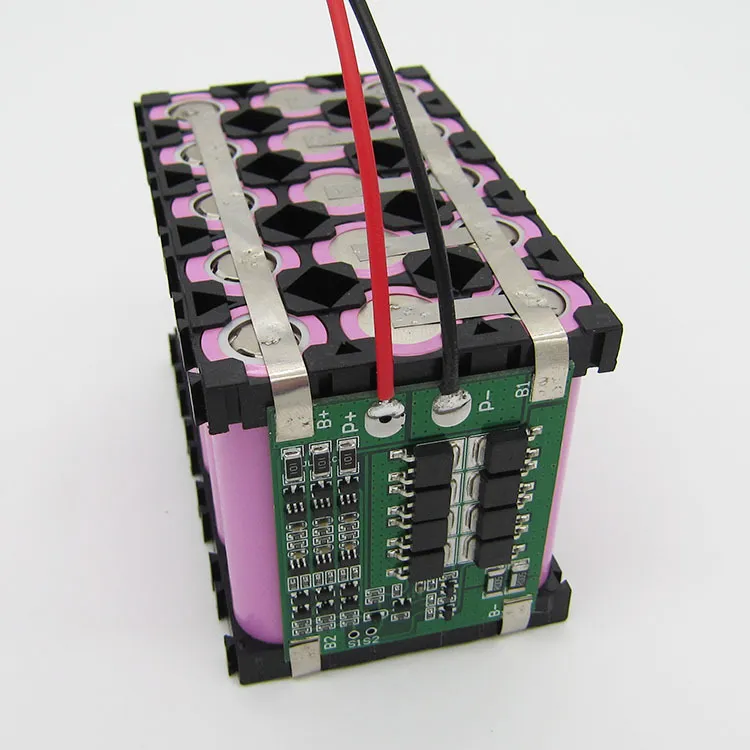
The protection board is typically integrated with the battery as one unit.
Input 5V → TP4056 → [Li-ion cell + Protection board (integrated)] → Buck/Boost → Various loads
↑____Charging____↑ ↑____Discharging____↑- Charging: TP4056 controls current into the battery; protection board monitors voltage.
- Discharging: current flows from battery through protection board, then DC/DC conversion to loads; protection board watches for over-discharge/short.
When setting TP4056 charge current, consider your USB source capability and thermals — the default 1A may be too high for small cells. The protection board MUST connect directly to the battery — not remotely on the main board. Common TP4056 modules on the market usually integrate the DW01+8205A already, forming a convenient all-in-one charge+protection solution.
6. Efficiency and Thermal Design — High Efficiency ≠ No Heat
A Buck at 95% efficiency delivering 50W still dissipates ~2.6W. That’s enough to make a MOSFET noticeably warm.
MOSFET loss sources: conduction loss P = I² × R_DS(on), plus switching loss (voltage-current overlap, significant at high frequency).
Think through the thermal path: MOSFET → thermal pad → metal frame/aluminum case → air. Many products use the enclosure itself as the heatsink — phone chargers, laptop power adapters all work this way.
My experience:
- Don’t get complacent because the efficiency number looks good. Calculate the absolute watts lost.
- Inductor DCR also generates heat — check it during selection.
- Thermal simulation or temperature-rise testing is not optional — make sure components stay below max junction temp at worst-case ambient.
- Vent holes, thermal interface materials — this is where mechanical and electrical design overlap.
7. The Three Questions Revisited, With a Case Study
Let me repeat those three questions — they really work:
- Input-output voltage difference? >3V and >0.3A → skip LDO, use Buck.
- System noise-sensitive? Wireless modules, precision analog → LDO or extra filtering.
- Space and thermals? Sealed tiny enclosure → go switching, avoid heat buildup.
Two Comparison Cases
- LM7805 (linear): 9V input → 7805 → output to Arduino. Run for 5 minutes, touch the chip — noticeably hot. ~55.6% efficiency.
- LM2596 module (Buck): adjusted to 5V output, same load. Barely warm. ~92.6% efficiency.
Conclusion: portable battery-powered products must prioritize switching supplies.
Teardown: Tracing Power in an Old Phone Charger
I tore down an old charger and traced the power path on the PCB — deeply satisfying:
AC 220V → fuse resistor → common-mode choke → bridge rectifier → 400V bulk electrolytic → transformer primary → switching IC → transformer secondary → Schottky rectifier → electrolytic filter → 5V USB outputKey component: the optocoupler straddles the high/low-voltage barrier, feeding back the output voltage while providing safety isolation. Now when I look at a board, my first reflex is to locate these blocks.
Core Takeaways
- Power design is energy distribution, not “making electricity.”
- LDO and Buck aren’t competitors — LDO is the low-noise, low-power solution; Buck handles high power with efficiency.
- Switching supplies are efficient, but absolute losses are still significant — thermal design is mandatory.
- Design chain: energy flow → voltage conversion → thermal path → mechanical integration. This is where EE and industrial design meet.
- Charge management (TP4056) sets the charging rules, the protection board is the safety net, DC/DC translates the voltage.
FAQ
Why must the protection board be integrated with the battery?
The protection board needs direct, zero-latency monitoring of cell voltage and current, usually spot-welded with nickel strips right onto the cell terminals. If placed on the main board with wires and connectors in between, resistance and loose connections seriously compromise protection reliability.
Can I charge a protected battery directly with TP4056?
Yes, this is the standard approach. TP4056 executes the CC/CV charge profile; the protection board acts as the last line of defense, cutting the circuit if voltage goes abnormally high.
Why is my Buck circuit still getting hot?
Even 1–2W of real loss will spike junction temperature without adequate cooling. Check inductor saturation current, MOSFET R_DS(on), PCB copper area, and the thermal path.
Knowledge Base — Module Reference Cards
Voltage Regulator Modules
| Module | Type | Vin | Vout | I_max | Efficiency | Heat | Use Case |
|---|---|---|---|---|---|---|---|
| LM7805 | Linear | 7-25V | 5V | 1.5A (w/ sink) | ≈Vo/Vin | High | Low current, noise-sensitive |
| LM2596 | Buck | 4.5-40V | Adj 1.25-37V | 2-3A | 85-93% | Low | Large voltage drop, efficiency-first |
Charge/Protection Modules
| Module | Function | Charge Method | Protection | Notes |
|---|---|---|---|---|
| TP4056+Protection | 1S Li-ion charging | Linear, 1A adj | OV, UV, OC, SC | Must pair with protection board |
Further Reading
AC-DC Topology Power Levels
Flyback
- Under ~100W, this is basically the default. Few components, low cost, isolated, multi-output capable.
- Applications: phone chargers, router power supplies, small appliances, LED drivers.
Forward
- Steps up from flyback, 100W+. Better efficiency, but more complex.
Push-Pull
- Higher power still. Common in automotive inverters, high-power DC/DC converters.
Half Bridge
- Server power supplies, industrial power, UPS.
Full Bridge
- Even higher power, widely used in the 1000W–5000W range.
LLC (Resonant)
- Modern PC power supplies all use this. Typical ATX PSU architecture: PFC → LLC → synchronous rectification → 12V, 90%–96% efficiency.
Switching Supply Ripple Mitigation
For sensitive circuits, add an LDO or π filter (C-L-C) after the Buck. The Buck+LDO combo gives you both efficiency and low noise.
Input DC → Buck → LDO → Load
-
Buck handles the “efficient rough step-down”
- Buck takes the big drop (e.g., 12V→5.5V) at 90%+ efficiency, generates very little heat.
- Steps down to just above the LDO’s final output (typically 0.3–0.5V headroom).
-
LDO handles “precision regulation and cleanup”
- Tiny dropout (0.3–0.5V), so P_loss is negligible — no heat problem.
- The LDO’s high PSRR crushes whatever ripple survived the Buck. Output is exceptionally clean DC.
Battery Selection and Power Tree Planning
Determine system voltage requirements first, then decide whether you need Boost or Buck-Boost based on battery characteristics (Li-ion 3.7V, NiMH 1.2V). Avoid major rework later.