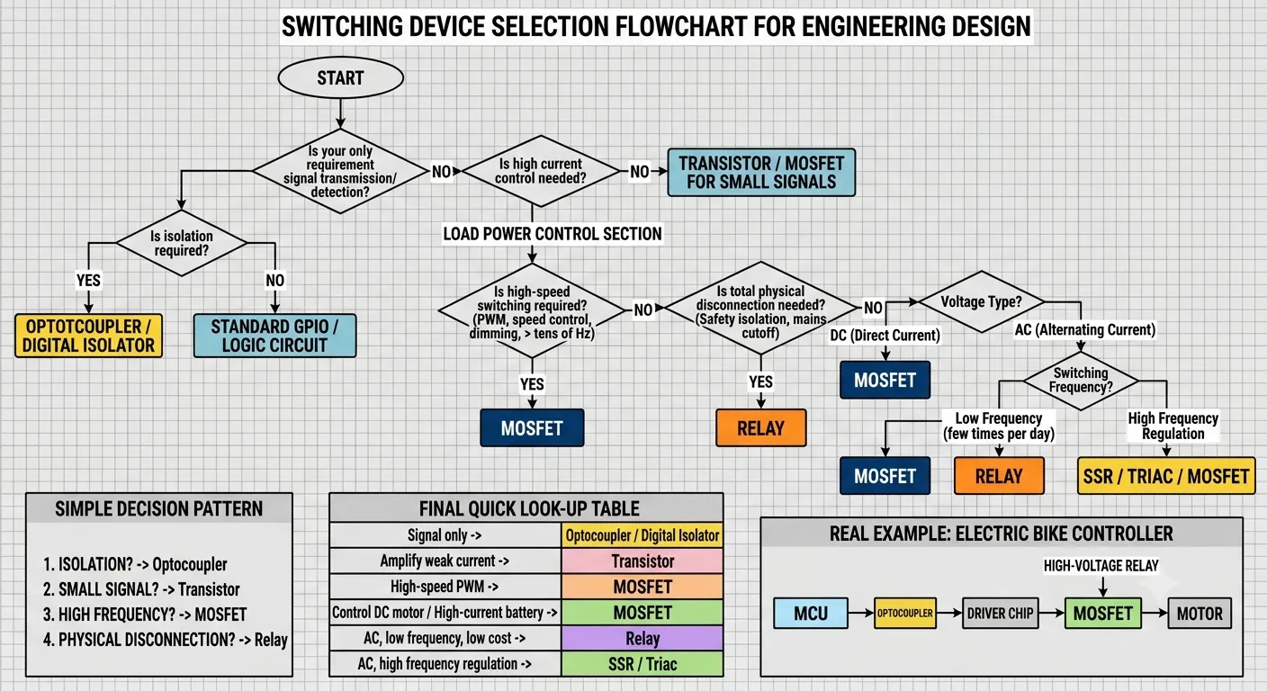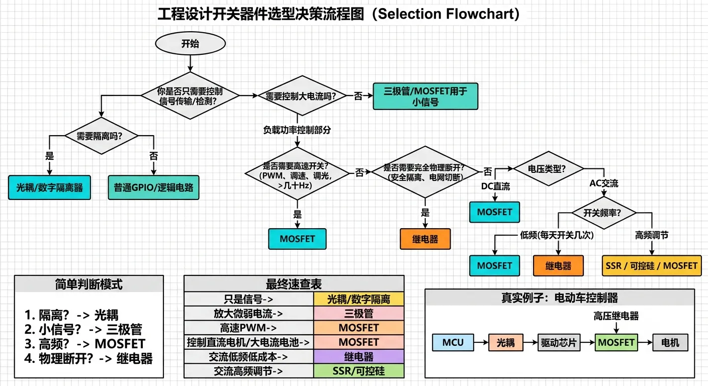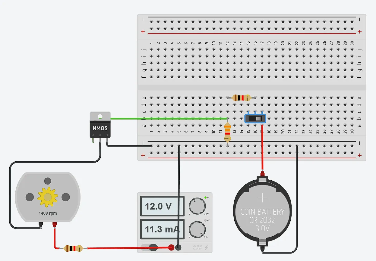
- MOS = the electronic switch between your MCU and high-power loads.
- Gate controls, Drain carries the load, Source goes to reference (usually GND for NMOS).
- GPIO doesn’t power the load — it only controls the Gate.
- NMOS + low-side switch + PWM is the most common driver topology in smart hardware. Master this first.
What GPIO Actually Is
GPIO is the MCU’s general-purpose input/output interface — configurable as input (sense external levels) or output (generate HIGH/LOW). But its essence is a digital control interface, not a power supply. HIGH ≈ 3.3V (or 5V), LOW ≈ 0V, representing logic 1 and 0. Its output current is severely limited — typically around 20mA.
That’s the core conflict: GPIO outputs 3.3V/20mA, but you need to drive a 12V/2A LED panel. Two orders of magnitude off. You need a “translator” — something that takes the MCU’s weak signal and controls the external power supply’s high current. That’s what a driver circuit does.
1. MOSFET Basics — Voltage-Controlled Electronic Switch
MOSFETs are perfect for this because they’re voltage-controlled: the Gate draws essentially zero continuous current — you just need enough voltage to turn it on. The MCU provides the control signal to the Gate via GPIO/PWM, and the load current flows from the external supply through the Drain-Source path. Two completely separate circuits.
Three Terminals
| Pin | Name | Role |
|---|---|---|
| G | Gate | Control input, virtually no steady current |
| D | Drain | Connects to load, carries the work current |
| S | Source | Current return (NMOS usually to GND) |
Key insight: the control signal and the load current travel through entirely separate paths. The GPIO only touches the Gate. The Drain-Source channel carries the external supply’s high current. They’re electrically isolated.
2. Why MCUs Can’t Drive Loads Directly
A 12V/24W LED panel needs 2A. An Arduino GPIO outputs ~20mA — a 100x gap. The MOSFET bridges it: the MCU provides the control voltage, the external 12V supply provides the current. Each does its own job.
3. NMOS vs PMOS
NMOS (Low-Side Switch) — Recommended
12V
 │
LED
 │
NMOS
 │
GND- NMOS sits between load and GND
- Gate is referenced to GND, so a 3.3V or 5V GPIO can drive it directly (assuming logic-level MOSFET)
- Simple circuit, low conduction loss, perfect for PWM
- This is where I started and what I use in most projects
PMOS (High-Side Switch)
12V
 │
PMOS
 │
LED
 │
GND- PMOS sits between supply and load
- To turn on PMOS, Gate must be pulled below Source by at least V_GS(th). Source is at 12V, so Gate needs to be near 12V - V_GS(th) — a 3.3V GPIO can’t do that
- Needs extra level shifting or a gate driver IC — more complex
- Not recommended for beginners
4. PWM Dimming
PWM doesn’t reduce voltage — it switches between full-on and full-off at high speed, varying the on-time ratio (duty cycle) to control average power. LEDs appear continuously lit (not flickering) thanks to persistence of vision, as long as the frequency is high enough.
- LED dimming: >200Hz avoids visible flicker. Arduino defaults of 490Hz/980Hz are fine
- Motor control: typically several kHz to 20kHz
- Too low → visible flicker or audible whine
- Too high → switching losses increase (MOS spends more time in the transition region)
5. Why You Need a Freewheeling Diode
Applies to: motors, fans, solenoids, relay coils — anything with a wound inductor.
When the MOSFET turns off, the inductor’s magnetic field collapses, generating a reverse high-voltage spike that can be several times the supply voltage — enough to blow the MOSFET’s Drain-Source junction. A freewheeling diode (1N4148 for low power, SS14 or similar Schottky for higher current) placed anti-parallel across the inductive load gives that stored energy a safe path to recirculate.
Pure resistive loads like LEDs generally don’t need one, but it doesn’t hurt to add it.
6. MOSFET vs BJT (NPN/PNP)
| Property | BJT (NPN/PNP) | MOSFET |
|---|---|---|
| Control method | Current-controlled | Voltage-controlled |
| Input impedance | Low | Extremely high |
| GPIO steady current | Required | Virtually none |
| Heat | Higher | Lower |
| High-freq PWM | Average | Excellent |
| High current | Average | Excellent |
BJTs are current-controlled: you have to keep feeding base current to stay on. MOSFETs are voltage-controlled: once the Gate capacitance is charged, basically zero current flows. In modern DC power switching, MOSFETs win across the board. BJTs still appear in analog circuits (amplification, linear regulation) and some high-voltage niches, but for driving loads from an MCU? MOSFET every time.
7. Relay vs MOSFET
| MOSFET | Relay |
|---|---|
| No mechanical contacts | Mechanical contacts |
| PWM capable | No PWM |
| Fast | Slower |
| Long life | Limited mechanical life |
| Silent | Audible click |
| DC only | AC/DC both |
I use a relay when: switching 220V AC, need true physical disconnect (zero leakage current), or need full galvanic isolation. I use a MOSFET when: LEDs, motors, fans, battery-powered products — DC loads that need speed, silence, and PWM control.
8. Optocoupler — When You Need True Electrical Isolation
An optocoupler transmits signals using light: an internal LED shines on a photosensitive receiver. There’s no conductive path between input and output — only photons. This lets a 3.3V MCU safely control 220V equipment, while also breaking ground loops and improving noise immunity.
Classic usage: MCU GPIO → current-limiting resistor → optocoupler LED → optocoupler transistor → driver circuit → TRIAC or relay → mains load. The low-voltage and high-voltage sides are completely isolated.
Industrial Product Analysis — My Framework
When I look at any product’s power stage, I ask five questions:
- Where does power enter?
- Which parts are the high-power loads?
- Who drives them (MOSFET/relay)?
- How does the MCU control them (GPIO/PWM)?
- What protection is in place (freewheeling diode, TVS, fuse, optocoupler)?
Common MOSFET-driven products: LED lights, RGB strips, fans, motors, water pumps, solenoid locks, solenoid valves, USB PD power supplies, Li-ion battery management, DC-DC converters, drone and EV motor controllers.
Design Notes — Lessons Learned
-
Always pick logic-level NMOS: standard MOSFETs often need ~10V Gate drive to fully turn on and hit their rated R_DS(on). A 3.3V GPIO simply can’t do it. Logic-level MOSFETs (like IRLZ44N — the “L” means Logic) achieve very low R_DS(on) at 3.3V or 5V. For 3.3V systems, verify this in the datasheet — check R_DS(on) at YOUR actual Gate voltage, not the headline number at V_GS = 10V.
-
Gate resistor is not optional
- Gate series 10-100Ω: the Gate looks like a capacitor. When GPIO switches, it has to charge/discharge that capacitance, and the instantaneous current can be surprisingly high. The series resistor limits this current to protect the GPIO pin and suppresses parasitic oscillation.
- Gate-Source pull-down 10kΩ: at power-up or when GPIO is high-impedance (input mode), the Gate can float. A floating Gate can partially turn on the MOSFET — high resistance, massive power dissipation, silicon death. The pull-down keeps the Gate firmly at 0V when not actively driven. Never skip this in production.
-
Inductive loads MUST have a freewheeling diode.
-
Common ground: the MCU’s GND and the power supply’s GND must be directly connected. Without a shared reference, the Gate drive signal has no return path and the MOSFET won’t switch. This is the #1 newbie trap. If you need isolation between MCU and load, use an optocoupler — don’t try to keep the grounds separate without one.
-
MOSFET selection checklist:
- V_GS(th) — gate threshold voltage (note: this is where it starts turning on, not fully on)
- R_DS(on) — on-resistance (lower is always better — heat = I² × R_DS(on))
- I_D max current (leave margin)
- V_DS max voltage (leave margin too)
-
PWM frequency: LED dimming >200Hz avoids flicker (Arduino 490Hz/980Hz is fine). Motor control several kHz to 20kHz. Too low → flicker/noise, too high → switching loss heat.