Electronics Fundamentals — My Self-Study Notes
These are the notes I’ve built up while systematically teaching myself hardware and analog electronics. Starting from the absolute basics — what voltage actually is, how current works, what a resistor looks like inside — with the goal of being able to look at a circuit board and understand what every component is doing. I come back to these notes regularly, and each time I find something new.
Note: Images are for educational and self-study purposes only.
Voltage and Current
The Water Analogy — A Decent Starting Point
Before diving into physics equations, use water pipes to build intuition:
- Voltage (V): equivalent to water pressure — the “push” that drives charges through a circuit, i.e., the potential energy difference
- Current (I): equivalent to water flow rate — the actual movement of charges through the conductor
- Resistance (R): equivalent to pipe diameter — narrower pipe, more resistance
Ohm’s Law: V = I × R
The analogy isn’t perfect (none are), but it’s good enough for a working mental model.
Deeper Understanding — What Actually Happens When You Flip a Switch
Flip a switch, the bulb lights instantly. So electrons must race from the battery to the bulb at light speed, right? No. Completely wrong. This was one of the most counterintuitive things I learned.
“Snail-Pace” Electrons vs “Light-Speed” Energy
Inside copper wire, free electrons fill the entire metal’s crystal lattice, forming what’s called an “electron sea” — they’re already everywhere in the wire.
-
Drift velocity: apply a voltage, the electric field pushes electrons forward. But they constantly crash into the copper atom lattice, so their net forward speed is incredibly slow — typically only a few micrometers to millimeters per second. Slower than a snail.
-
So why does the bulb light instantly? Because energy isn’t carried by the electrons themselves — it’s carried by the electromagnetic field. The moment the switch closes, the electric field propagates along the wire at nearly the speed of light (~3 × 10⁸ m/s). The electrons are already everywhere in the wire; the field gives all of them the push (F = qE) simultaneously, and they all start drifting together.
This was a real “aha moment” for me — electrons barely move, but the field travels at light speed. What we call “electricity” is really field propagation.
The Essence of Voltage: Spatial Accumulation of Electric Field Force
In physics, voltage is electrical potential difference. A battery uses chemical energy to forcibly separate positive and negative charges, creating an electric field in space. Electrons moving through this field have work done on them by the field force. Voltage is that work, per unit charge.
So voltage isn’t some mysterious gas pressure — it’s the “invisible push” of the electric field on charges, accumulated over a spatial distance.
Kirchhoff’s Laws
These two laws aren’t just handy circuit analysis tools. Behind them stand two fundamental conservation laws of the universe: conservation of charge and conservation of energy.
Kirchhoff’s Current Law (KCL)
Why Electrons Can’t Just Pile Up at a Node
- Formula: Σ I_in = Σ I_out
- The physics: electrons carry negative charge. According to Coulomb’s Law, like charges repel each other with enormous force. If more electrons flowed into a node than left, negative charge would accumulate there.
- Self-correcting mechanism: the instant charge starts building up, the repulsive force pushes away incoming electrons and accelerates outgoing ones. This microscopic self-balancing happens in nanoseconds. Under steady-state conditions, no node can hold excess net charge. What goes in comes out — exactly.
Kirchhoff’s Voltage Law (KVL)
Why a Full Loop Always Sums to Zero
-
Formula: Σ V = 0
-
The physics: in electrostatics and low-frequency circuits, the electric field is a conservative field (irrotational). The work done by the field force depends only on the start and end points, not the path taken.
-
The energy picture: think of the power source as a “charge elevator” — it consumes chemical energy to lift electrons from low potential to high potential. As electrons flow through resistors, they give up all that potential energy through collisions with the atomic lattice, converting it into heat or light. By the time an electron returns to the battery’s negative terminal, all the energy it gained has been surrendered. Energy can’t be created or destroyed — that’s KVL at its core.
Basic Electronic Components
Resistor
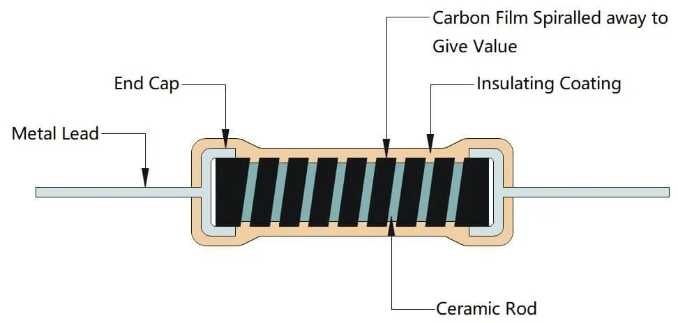
Resistors are passive components whose job is to impede current flow. Two main uses: current limiting (so your LED doesn’t burn out) and voltage division (creating reference levels).
Inside a Carbon Film Resistor
- Ceramic core: a solid rod of high-grade ceramic (insulator) — the structural foundation.
- Carbon film layer: a thin layer of pure carbon deposited on the ceramic surface. This is the actual resistive material.
- Helical groove: a spiral is laser-cut into the carbon film. Shorter, wider spiral = lower resistance; longer, thinner = higher resistance. The spiral geometry sets the value.
- End caps and leads: metal caps press-fit onto both ends, tinned copper leads welded to the caps.
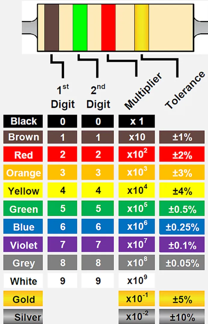
- Protective coating and color bands: insulating lacquer with colored stripes encoding the resistance value and tolerance.
LED Current Limiting
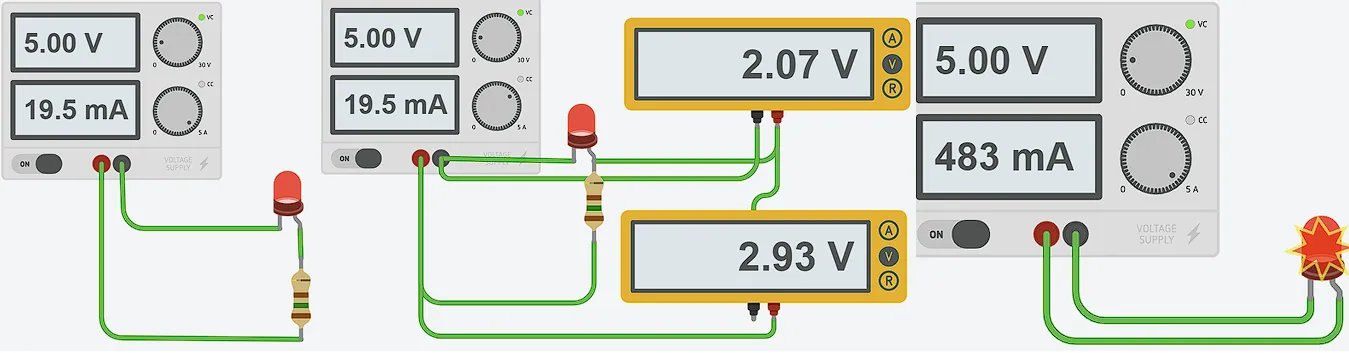
Probably the first resistor circuit everyone builds: LED + series resistor. Without the resistor, the LED pulls as much current as the supply can give until it destroys itself.
Voltage Divider
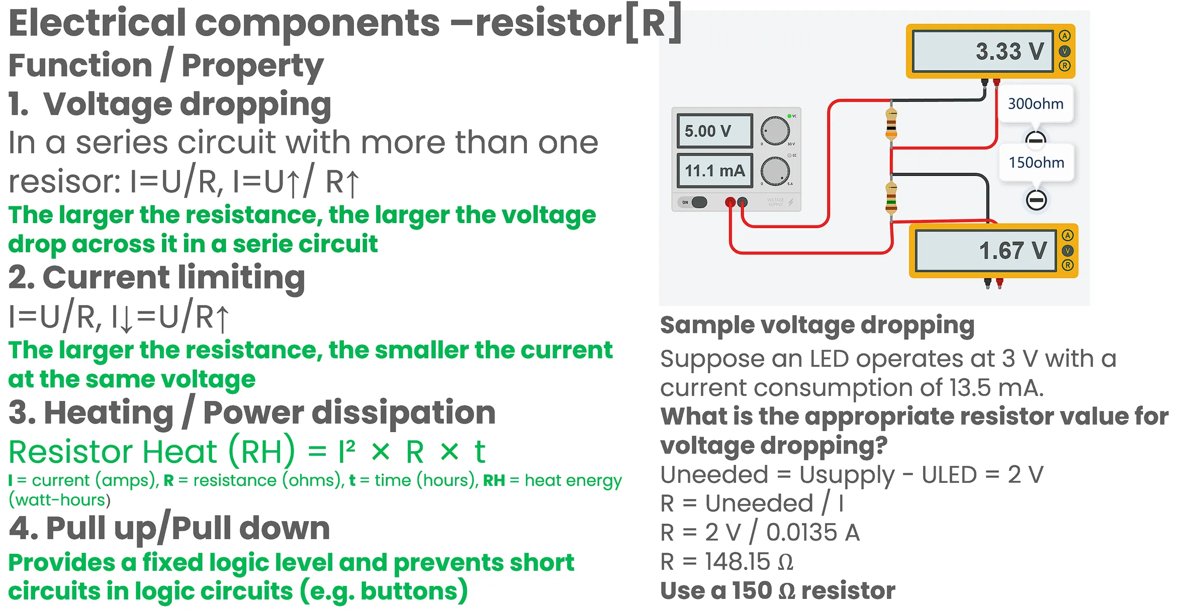
In a series circuit, voltage drop across each resistor is proportional to its resistance (bigger R = more voltage share).
Practical calculation — sizing a series resistor for an LED: LED operates at 3V, draws 13.5mA (0.0135A), using a 5V supply.
- V_drop = V_source - V_LED = 5V - 3V = 2V
- R = V_drop / I = 2V / 0.0135A = 148.15Ω → use a 150Ω resistor
Can an LED Work as a Resistor?
No. An LED is a diode — it’s nonlinear. A resistor follows Ohm’s law (current proportional to voltage). An LED’s I-V curve is exponential: below the forward voltage it barely conducts; above it, current skyrockets. You can’t replace it with a fixed resistance.
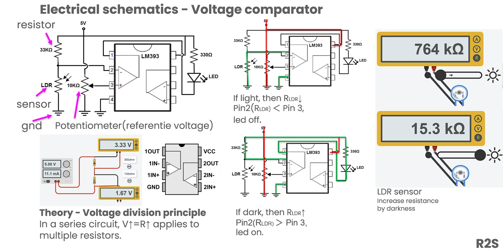
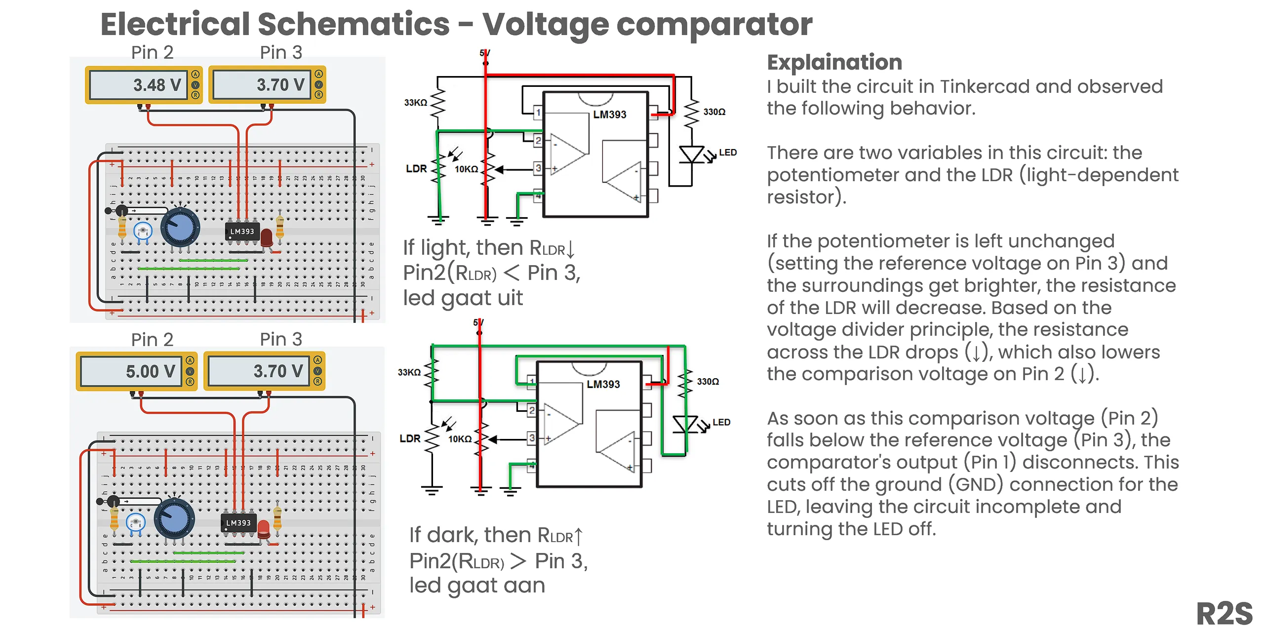
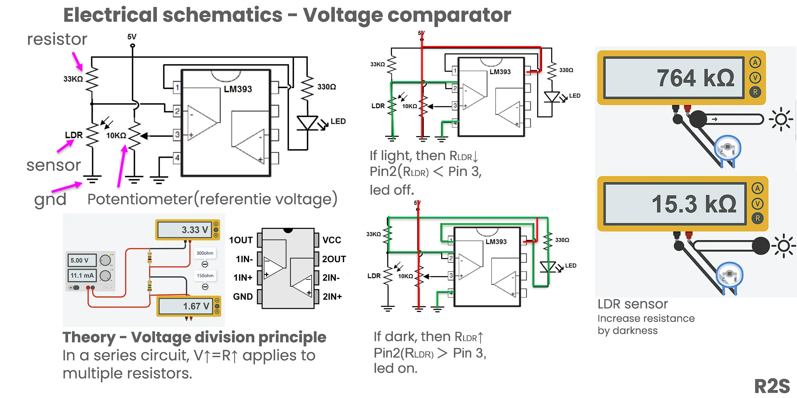
Practical Case: Voltage Comparator
Resistor Types
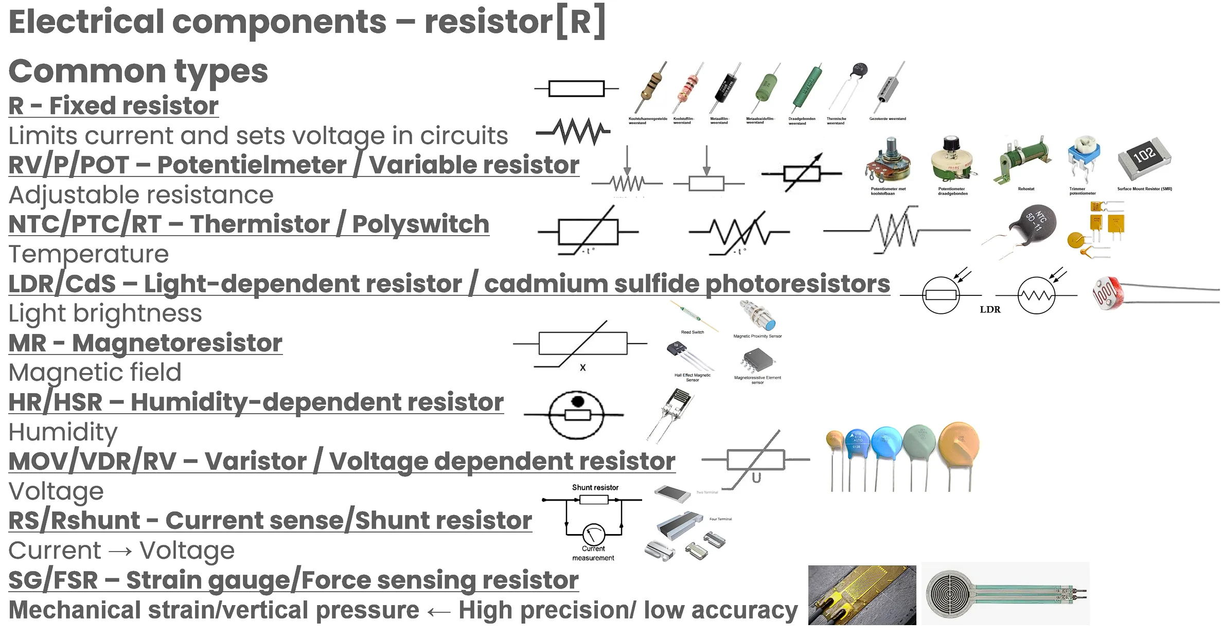
There’s quite a variety: carbon film, metal film, wire-wound, SMD chip resistors, potentiometers (variable resistors). Selection depends on power rating, tolerance, temperature coefficient, and noise requirements. I default to metal film for analog circuits — lower noise than carbon film and better temperature stability.
Resistor Summary
Capacitor
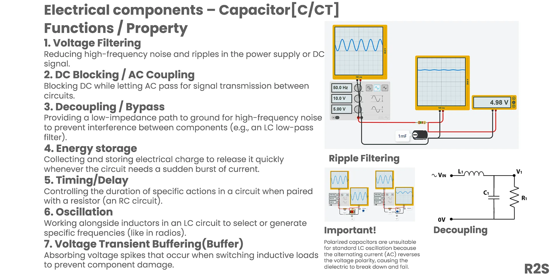
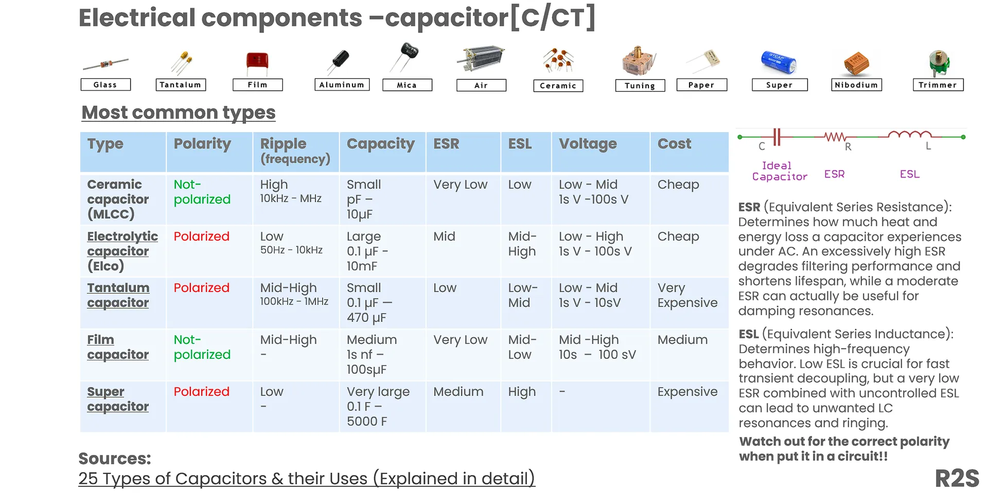
Capacitors store energy in an electric field between two conductive plates separated by a dielectric (insulator). Used for filtering, decoupling, timing circuits, and energy storage. Key formula: I = C × dV/dt — current through a capacitor is proportional to the rate of voltage change.
Inductor
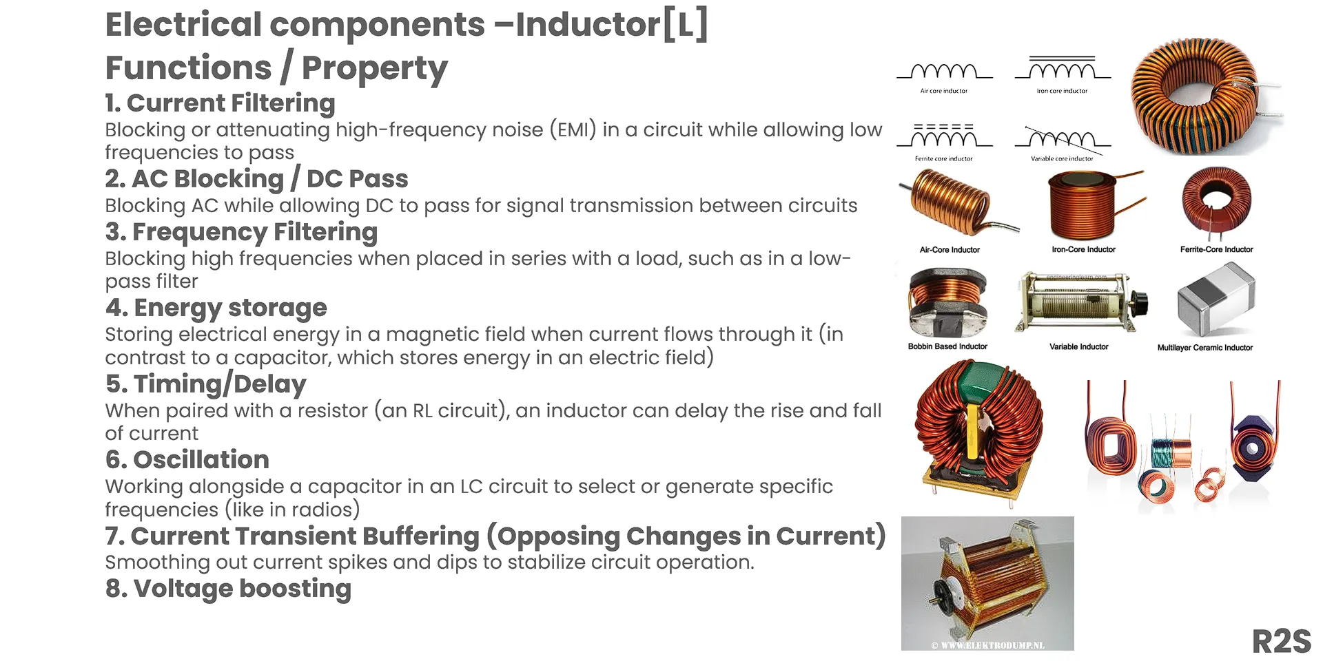
Inductors store energy in a magnetic field when current flows through them. It’s a coil of wire, typically wound around a magnetic core. Its defining behavior: it resists changes in current. Key formula: V = L × dI/dt — voltage across an inductor is proportional to the rate of current change.
Practical Case: Rectifier Bridge LC Filter
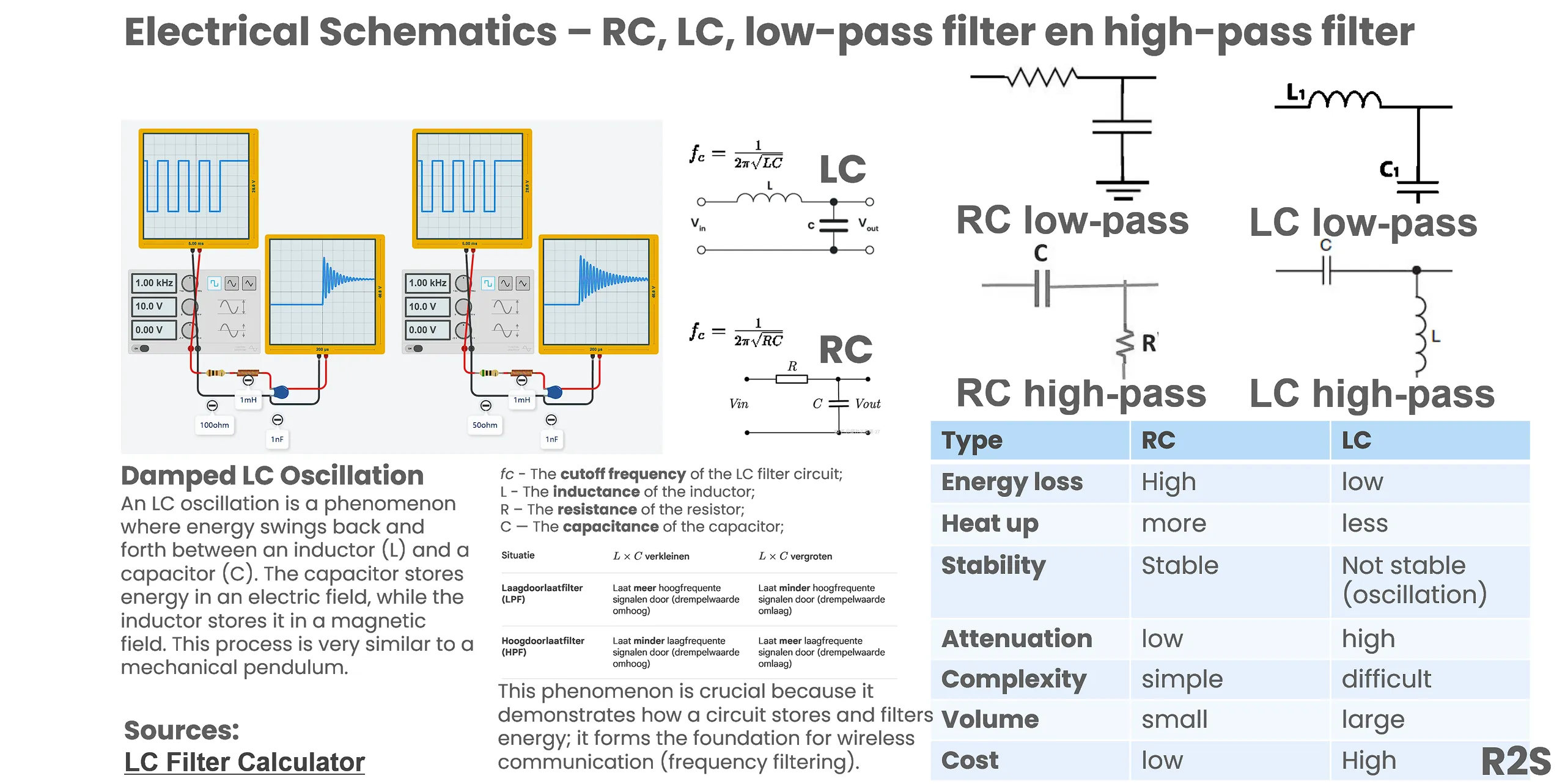
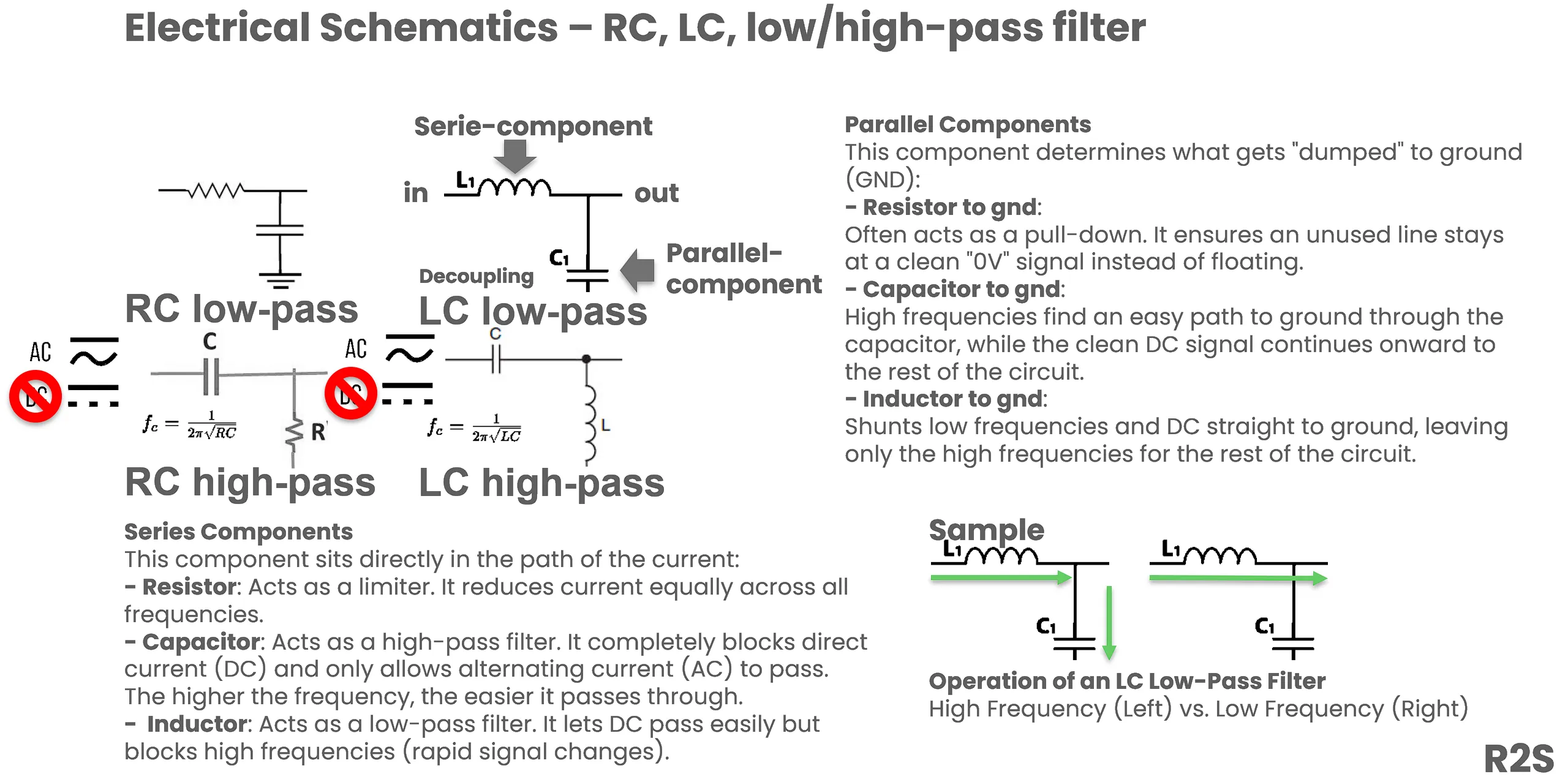
In power supply circuits, inductors and capacitors work together as LC filters. After the bridge rectifier converts AC to pulsating DC, the inductor suppresses ripple current and the capacitor smooths the voltage. The resulting DC is much cleaner than capacitor-alone filtering.
Diode
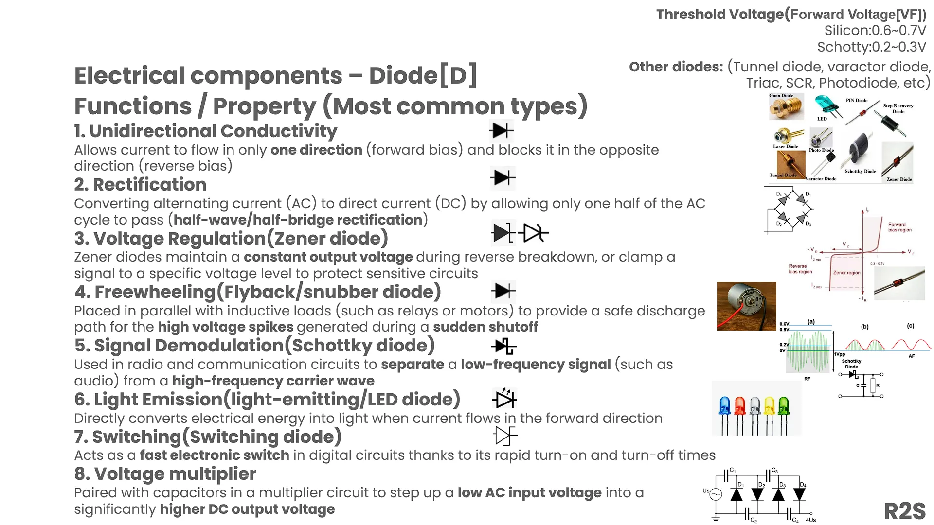
Diodes only allow current flow in one direction — anode to cathode. They’re the foundation of rectification (AC→DC), reverse-polarity protection, and all kinds of signal processing. Forward voltage drop: ~0.7V for silicon diodes, ~0.2-0.4V for Schottky diodes.
Practical Case: Rectifier Bridge
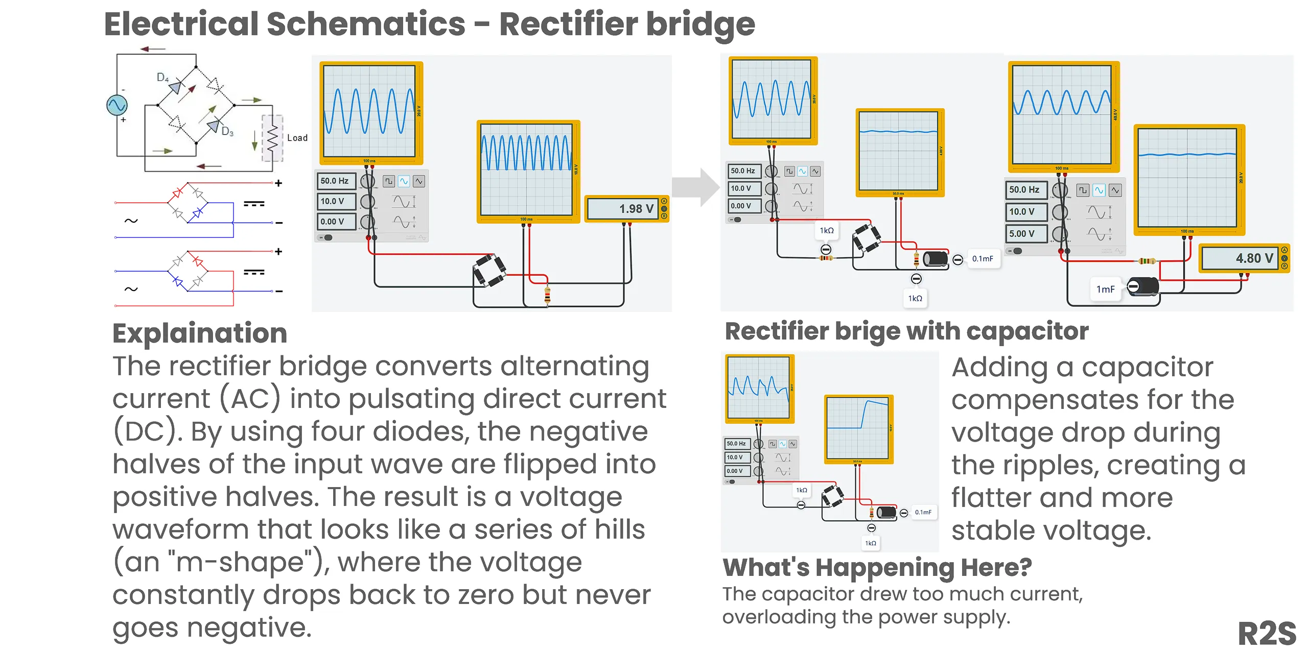
Four diodes arranged as a bridge rectifier convert AC to pulsating DC. The capacitor after the bridge smooths it into something usable. This is the front end of basically every linear power supply.
Transistor
🚧 Coming soon — transistor content in progress.
MOSFET
🚧 Coming soon — MOSFET content to follow.
Linear vs Switching Power Supplies
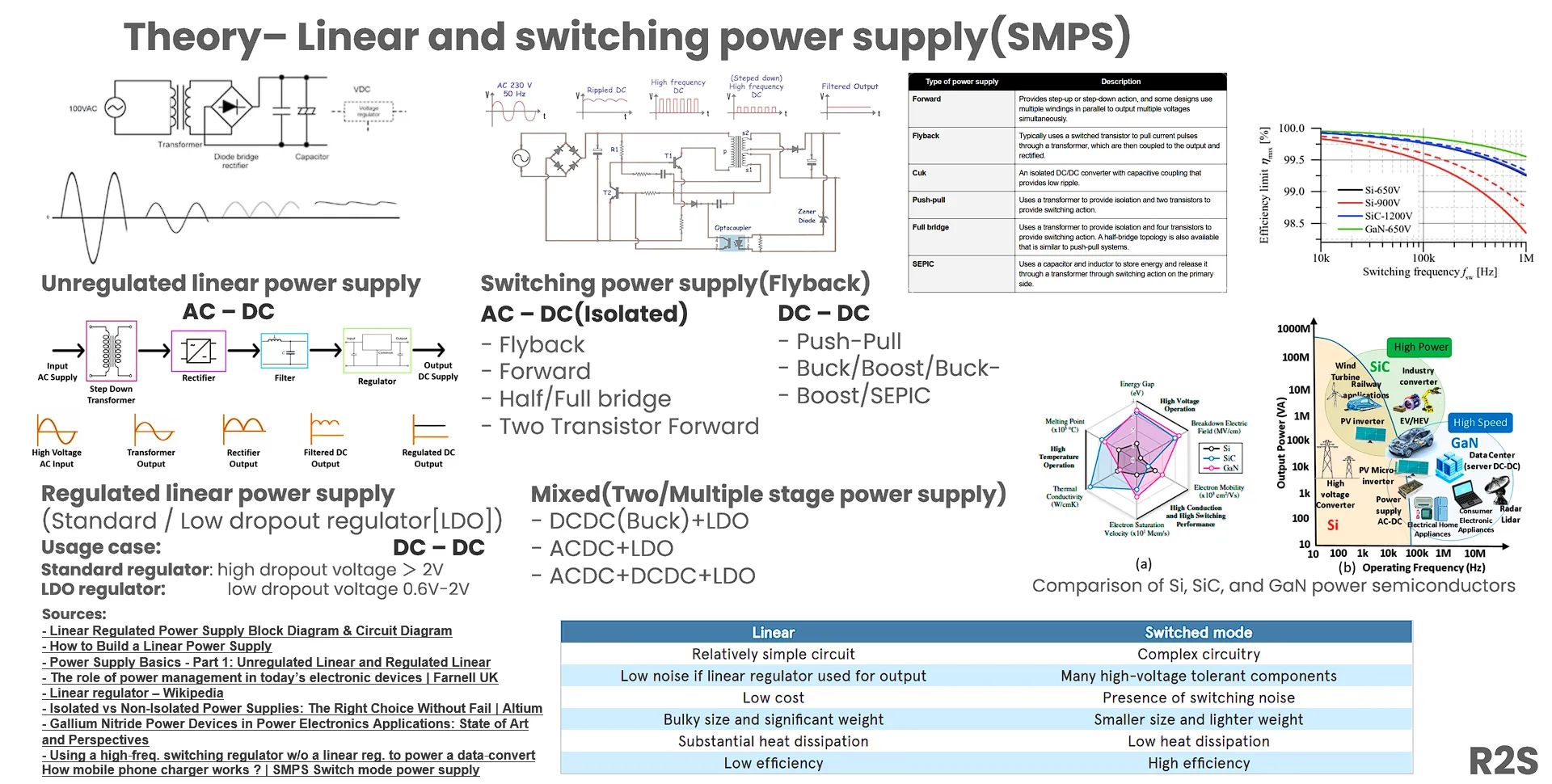
Power supplies convert input power into regulated DC output. Two main topologies:
- Linear supply: transformer → rectifier → filter cap → linear regulator. Simple, low noise, but inefficient — excess voltage all becomes heat.
- Switching supply (SMPS): high-frequency switching → transformer → rectification → feedback control. More complex, but far more efficient and much smaller.
Practical Case: 230V → 12V Switching Power Supply
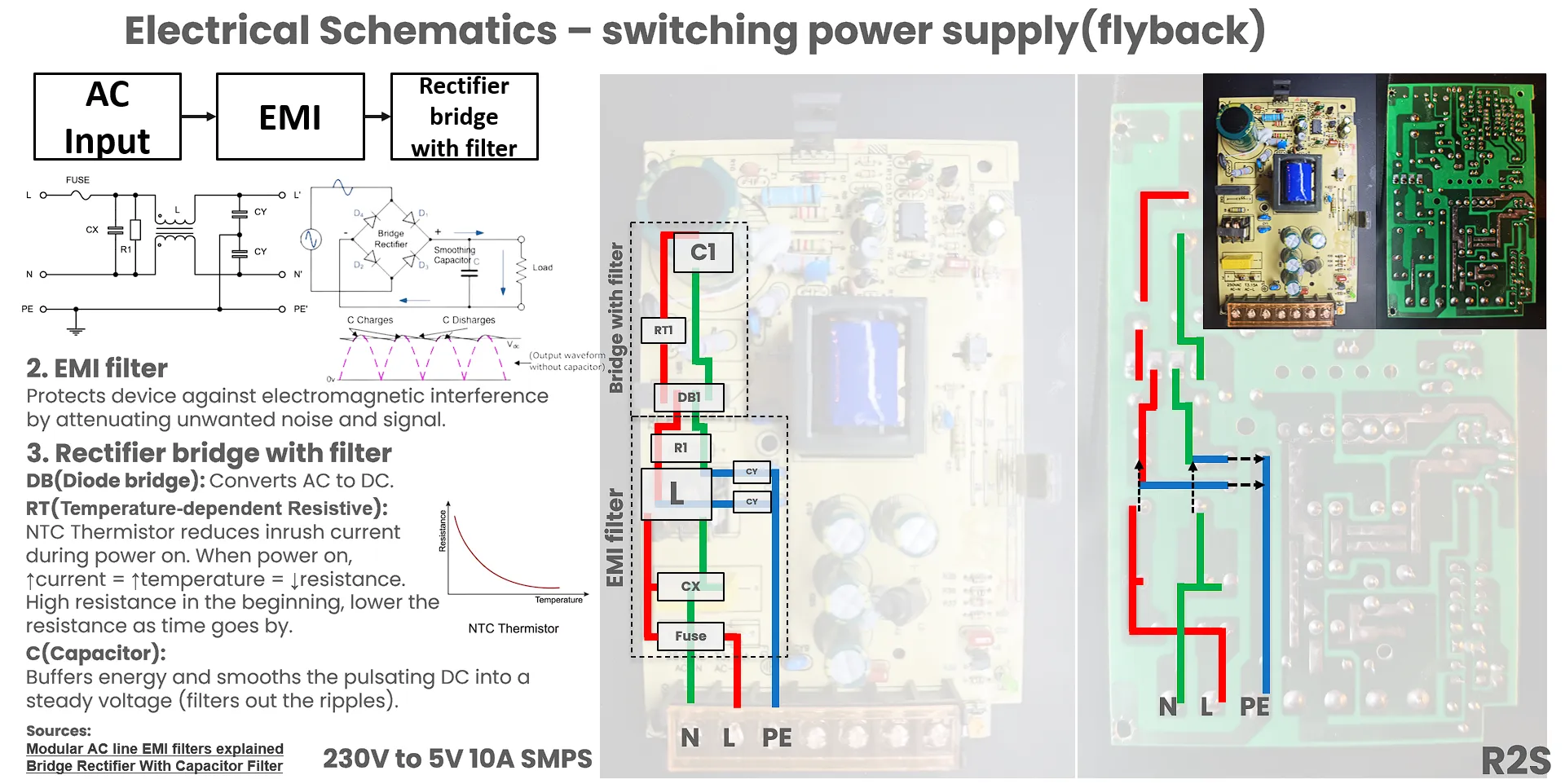
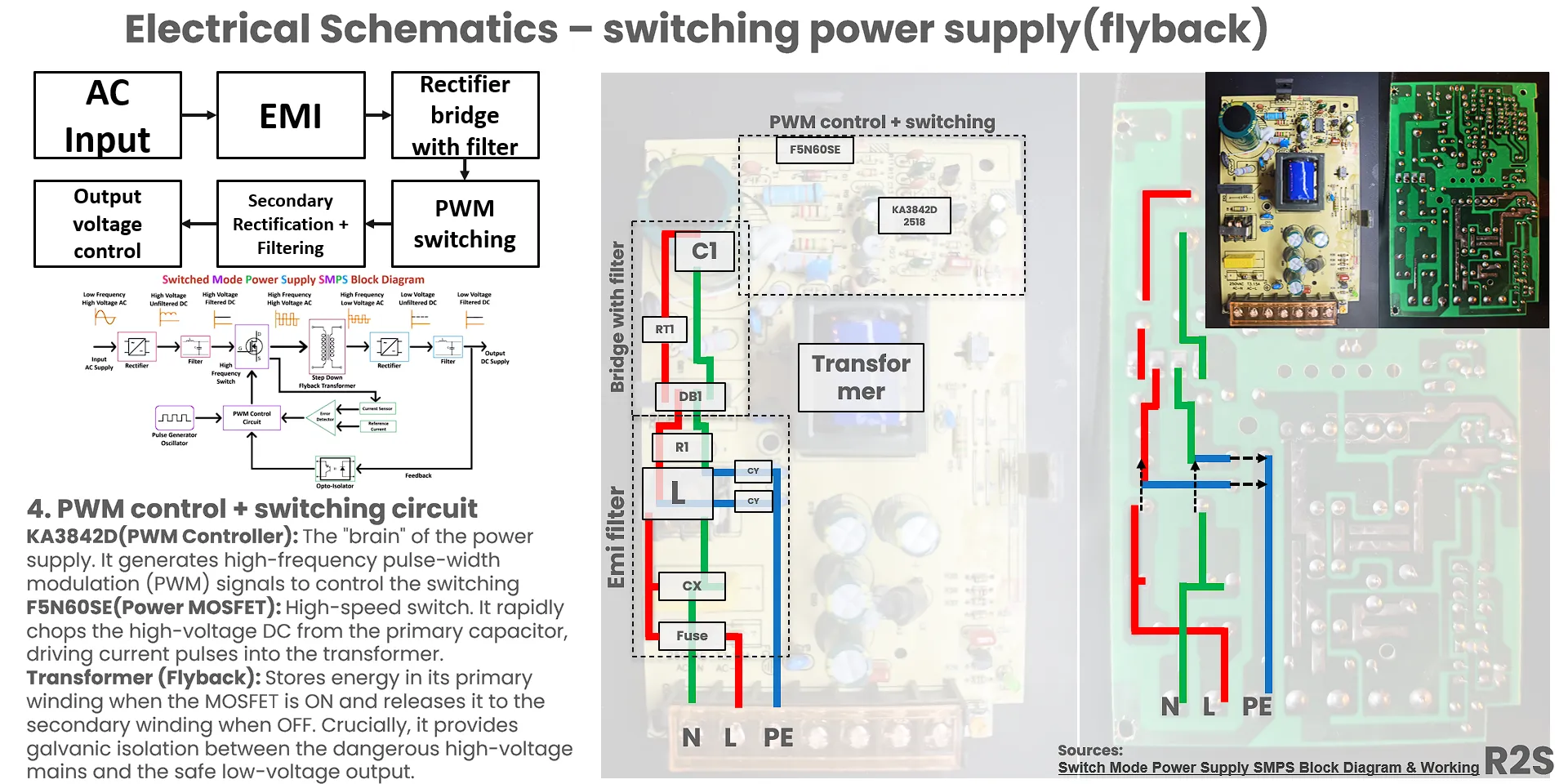
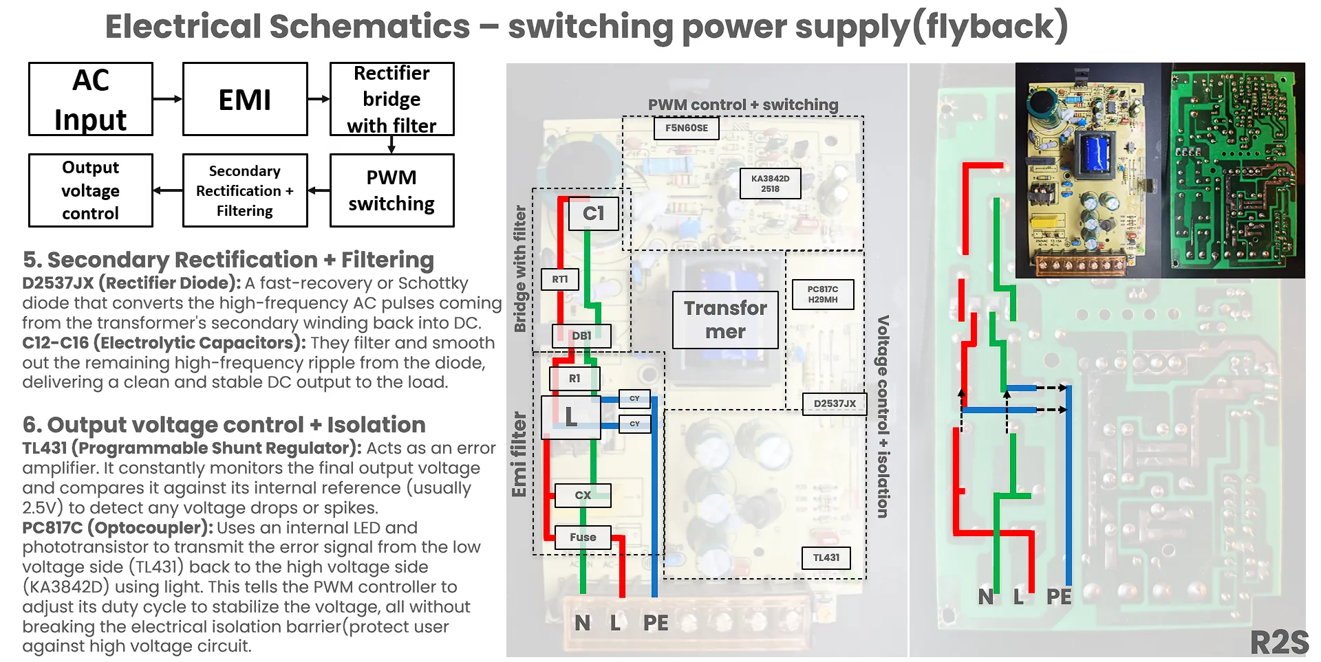
Walking through an SMPS schematic stage by stage — input filtering, bridge rectifier, switching controller, transformer, output rectification, feedback loop — is a great way to understand real power supply design.
Practical Skills
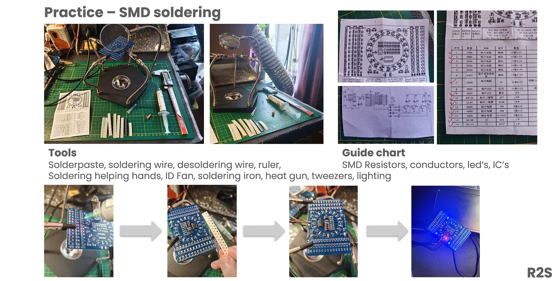
The hands-on skills I’m building: breadboarding circuits, soldering, using a multimeter correctly, reading schematics, basic troubleshooting. Theory only takes you so far — the moment you find that loose ground connection with a multimeter, a lot of theory suddenly clicks.
References
- LED Resistor Calculator
- Resistor Heat Calculator
- Pull-Up and Pull-Down Resistors
- LM393 Voltage Comparator Datasheet | TI.com
- How to Build a Voltage Comparator Circuit Using an LM393
- LC Filter Calculator
- Voltage and Current Explained
- 25 Types of Capacitors & Their Uses
- Linear Regulated Power Supply Block Diagram & Circuit Diagram
- How to Build a Linear Power Supply
- Power Supply Basics — Part 1
- Isolated vs Non-Isolated Power Supplies
- Gallium Nitride Power Devices in Power Electronics
- How Mobile Phone Chargers Work | SMPS
- Modular AC Line EMI Filters Explained
- Bridge Rectifier With Capacitor Filter
- Understanding Carbon Film Resistors
- Resistor Color Codes: Color Band Meanings