Article: Purpose and Principles of Pull-Up and Pull-Down Resistors — Zhihu
What a Button Actually Is
A button is just a mechanical switch. That’s it. It doesn’t “tell” the MCU anything — all it does is connect or disconnect two metal contacts. Not pressed: ── ──, pressed: ──────.
The MCU can’t sense the button directly. It only reads voltage on a GPIO pin. So the whole chain is: mechanical action → GPIO voltage change → MCU reads voltage → firmware decides state. The button changes the circuit; the MCU reads the result.
The Floating Problem
The simplest possible wiring: GPIO — Button — GND. Pressed = GPIO pulled to GND = LOW. That works. But when it’s NOT pressed? The GPIO pin is connected to nothing. It floats. The voltage is undefined — anywhere between 0V and 3.3V, completely at the mercy of nearby electric fields and noise. The MCU reads random garbage.
This is why you need a pull resistor: it gives the GPIO a known default state.
A Beginner Mistake
Someone might think: 5V → GPIO → Button → GND. When not pressed, GPIO sits at HIGH. Looks fine. But the moment you press the button — 5V shorts straight to ground through the GPIO’s internal protection diodes (or the IO transistors). The path resistance is near zero, current spikes massively. At best you fry the IO pin. At worst, the whole chip.
Never do this.
The Right Way
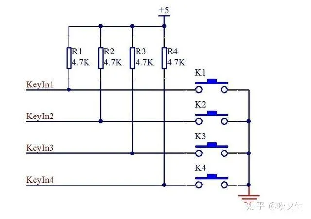
5V → 10kΩ resistor → GPIO + Button → GND- Not pressed: 5V charges the GPIO pin through the 10kΩ resistor. GPIO input impedance is megohm-level (nearly an insulator), so it draws almost no current. Barely any voltage drops across the resistor — the pin sits at a solid HIGH.
- Pressed: GPIO gets shorted straight to ground = LOW. Current = 5V / 10kΩ = 0.5mA. That’s tiny — safe, efficient, and the pin gets pulled reliably to 0V.
This is “weak pull-up, strong pull-down” in action: the resistor’s pull is weak enough that the button’s direct short to ground easily overrides it, but strong enough to hold the pin HIGH when the button is open.
Pull-Up vs Pull-Down
3.3V
│
10kΩ
│
●──── GPIO
│
│
Button closed
│
GND
Pull-up: resistor from VCC to GPIO. Default = HIGH, pressed = LOW (active-low). Pull-down: resistor from GPIO to GND. Default = LOW, pressed = HIGH (active-high).
Simply put, a resistor from power to GPIO is a pull-up — it clamps the pin HIGH by default. A resistor from GPIO to ground is a pull-down — it clamps the pin LOW. Both also limit current: without the resistor, pressing the button is a dead short.
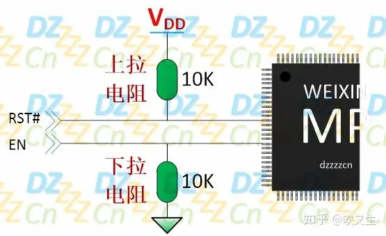
Key functions of pull resistors:
- They set a known default state, preventing floating and false triggers. At power-up, the pin level is uncertain — a pull-up guarantees it starts HIGH and won’t glitch.
- They can help output pins drive heavier loads. If the output HIGH can’t quite reach VCC due to peripheral loading, a pull-up gives it a boost.
Why Current Takes the Button Path, Not the GPIO
GPIO input impedance is extremely high — it draws almost no current, it only senses voltage. When the button is pressed, its resistance is near zero, so the current path is: 3.3V → 10kΩ → Button → GND. I = 3.3V / 10kΩ ≈ 0.33mA. The 10kΩ provides both the default level and the current limit.
Why Not Wire GPIO Directly to 3.3V?
Bad design: 3.3V directly to GPIO and button to GND. Press the button and 3.3V shorts straight to ground. Massive current surges through — things heat up, protection circuits trip, components burn. You MUST have a current-limiting resistor in series.
Why 10kΩ?
Common pull resistor values: 4.7kΩ, 10kΩ, 22kΩ, 47kΩ.
- Lower resistance → stronger pull, better noise immunity, but more power burned
- Higher resistance → less power, but more susceptible to noise
- 10kΩ hits the sweet spot: 3.3V/10kΩ = 0.33mA, negligible power, reliable noise immunity. It’s the industry default for a reason.
Whether to pull up or down depends on the system. An active-high enable signal (EN) that should default to inactive → use pull-down. An active-low reset (RST#) that should default to inactive → use pull-up. For motor control, a floating pin could get noise-triggered to HIGH and spin the motor by accident — a pull-down locking the default to LOW is critical there.
Resistors also come in strong vs weak pull. Internal MCU pull resistors are typically weak (high value, 20kΩ~50kΩ). Lower resistance = stronger pull, better noise immunity — external noise needs more energy to flip a strongly-pulled pin. But lower resistance also means more power. It’s a fair trade-off.
Why Buttons Bounce
Mechanical buttons aren’t ideal switches. When you press one, the metal contacts don’t close cleanly — they collide, rebound, collide again, rebound again, producing a burst of rapid ON-OFF-ON-OFF-ON transitions over several milliseconds (sometimes tens of ms). On an oscilloscope, a single press looks like a dense pulse train. A fast MCU can easily count each bounce as a separate press.
Debounce
Software debounce: Detect pin change → wait ~20ms → read again → confirm it’s still the new state → act. Zero hardware cost, good enough for most cases.
Hardware debounce: RC low-pass filter (e.g., 10kΩ + 100nF). fc = 1/(2πRC) ≈ 159Hz, while mechanical bounce is in the kHz range — over an order of magnitude apart, so the filtering is very effective. A Schmitt trigger input cleans up any remaining ripple.
Many products use both: RC for the first pass, software for confirmation. Solid.
Production-Grade Button Circuit
3.3V
│
10kΩ
│
GPIO────┼────100nF────GND
│
Button
│
GND- Button: user input
- 10kΩ: pull-up, anti-float, current limiting
- 100nF cap: hardware debounce, noise filtering
- GPIO: state detection
What Industrial Designers Should Know
Mechanical design: button size, travel, actuation force, rebound speed, assembly tolerances, long-term wear. Environmental reliability: water/dust resistance (IP rating), ESD protection, EMC immunity. User experience: single click, double click, long press, repeat trigger, state feedback (haptic/visual/audio). Product lifetime: rated cycle count, mechanical fatigue, temperature effects on materials.
Mice, keyboards, remotes, rice cookers, humidifiers, smart lights, electric toothbrushes — the button circuit logic behind all of these is exactly the same: user input → button → GPIO → MCU → execute function.
Core Summary
A button doesn’t send a signal to the MCU — it changes the GPIO voltage state, and the MCU reads the logic change. Core circuit: 3.3V → pull-up resistor → GPIO node → button → GND. Core idea: the resistor provides the default state and limits current, the button changes the circuit, the GPIO reads the result.
FAQ
Why Pull-Up Dominates in Industrial Design
1. Built-In MCU Pull-Ups Are Free
Most MCUs (STM32, ESP32, Arduino) have programmable internal pull-up resistors. Internal pull-downs are rarer or weaker. Enable the internal pull-up and you save a resistor and PCB space — zero BOM cost. Engineers naturally reach for the free option, and over time this created a “pull-up first” design culture.
2. Fail-Safe — This Is the Critical One
- In a pull-up circuit, pressed = LOW.
- If the wire between button and board breaks, a connector comes loose, or a solder joint cracks, the pull-up immediately yanks the floating GPIO back to a solid HIGH — “not pressed.”
- Result: the failure does NOT cause a false trigger. The system stays safe.
Flip it around: with pull-down, a broken wire leaves the GPIO LOW — “always pressed.” The system might trigger continuously, enter infinite loops, or create actual safety hazards. In industrial equipment, automotive electronics, and any reliability-critical domain, fail-safe to idle is mandatory.
3. Ground as Reference Is More Reliable
- The ground plane is the 0V reference for the entire system — widespread, ultra-low impedance, excellent at absorbing and shielding noise, far better than the power rail.
- Static or noise from a finger touch gets safely shunted to earth rather than injected into the sensitive power rail.
- With active-low signaling, noise has to push the level above VIH (~0.7 × VCC) to register. The power rail has decoupling caps that make noise coupling harder. Active-high noise margins are inherently worse.
4. Power and Logic Naturally Align
- Quiescent power: when not pressed, both ends of the pull-up are HIGH — virtually zero power. Pressed = 3.3V/10kΩ = 0.33mA, consumed only during the action. A pull-down scheme produces the same current (VCC through button to pull-down), so there’s no static power advantage either way.
- Logic intuition: many sequential logic circuits (reset circuits, etc.) use active-low signaling. Pull-up + button-to-ground naturally gives “pressed = 0”, matching interrupt triggers and reset logic — less mental overhead when writing firmware.
5. Open-Drain and Bus Compatibility
When multiple devices share a signal line (I²C, 1-Wire, or a button sharing a pin with a status indicator), open-drain + pull-up is the standard topology. Pull-up slots right in. Pull-down needs extra level translation or circuit rework.
When Would You Actually Choose Pull-Down?
Not every design rejects pull-down:
- Active-high requirement: some peripheral reset or enable pins are active-high. For logic consistency, design the button to output HIGH when pressed → use pull-down.
- Ultra-low-power wake-up pin limits: some ultra-low-power MCUs only support rising-edge or high-level wake-up. You must use pull-down with the button tied to VCC.
- Short-to-supply safety: in automotive environments where the button-to-VCC wiring harness might accidentally short to chassis ground, pull-down prevents the short. But this is far less common than the pull-up case.
Further Reading
Internal vs External Pull-Up
MCU internal pull-ups (20kΩ~50kΩ) save components, but they’re high-value and weak. In long traces or noisy environments, they’re not reliable enough. Industrial products often add an external 10kΩ even when the MCU supports internal pull-ups — lower resistance, stronger noise immunity. The designer chooses based on trace length, ambient noise, and power budget.
Debounce State Machine
A simple delay(20ms) only handles basic clicks. Production-grade interaction needs a state machine: IDLE → press detected → DEBOUNCE_PRESS (wait 20ms confirm) → PRESSED (execute, enter release debounce) → release detected → DEBOUNCE_RELEASE (wait 20ms confirm) → back to IDLE. This framework prevents long-press retriggering and is the foundation for double-click, long-press, and other gestures.
Polling vs Interrupt
Polling: main loop or timer periodically reads GPIO. Simple but burns CPU, bad for low power. Interrupt: button on interrupt pin, edge-triggered ISR, start a timer in the ISR for debounce. Lower power, faster response — essential for battery-powered devices. Real products often combine both: interrupt wakes the system, then polling handles debounce.
Quantitative Hardware Debounce Design
RC filter (10kΩ + 100nF): fc = 1/(2πRC) ≈ 159Hz, far below the mechanical bounce frequency (kHz range), so filtering is very effective. τ = RC = 1ms. With a Schmitt trigger, residual ripple gets further suppressed. Tune the capacitor value based on actual bounce characteristics — balance response speed against filtering.
Safety and Reliability Design
GPIO mode misconfiguration protection: if GPIO accidentally gets set to push-pull output HIGH and the button is pressed, you get a short. Place a 100Ω~1kΩ protection resistor between GPIO and the button node to limit fault current to a safe range (e.g., 3.3V/100Ω = 33mA). ESD protection: buttons are direct human-touch paths. Always add a TVS or dedicated ESD protection diode to ground — shunts the zap away before it reaches the MCU.
Multi-Button and GPIO Optimization
Single-button design only works for a few buttons. When you have many, the industry uses matrix scanning (row/column) or ADC resistor-ladder (a chain of resistors dividing voltage, one ADC pin reads different voltages for different buttons) to dramatically save GPIO pins.