Overview
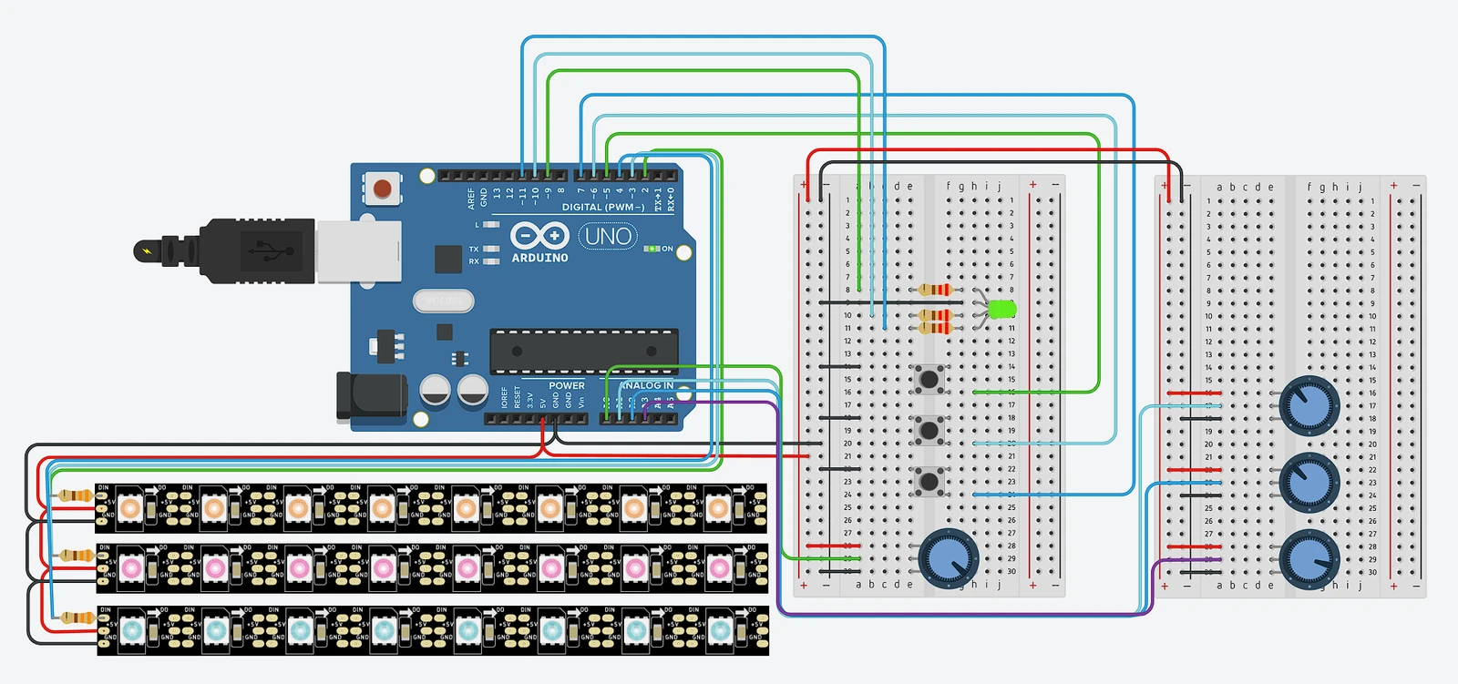
Before committing to real hardware, I wanted to prototype a multi-channel LED controller in simulation first. Tinkercad Circuits is surprisingly capable for this kind of thing — it gives you a virtual Arduino, NeoPixel strips, pots, buttons, and a working serial monitor, all without soldering anything.
The circuit controls three independent NeoPixel strips. Three push buttons let you pick which strip is “active,” and four potentiometers handle the color mixing: three for RGB, one for master brightness. The currently-selected strip gets updated in real time, while the other two hold their last state. A small status LED mirrors the active channel color so you can tell at a glance which strip you’re editing.
Controls
- 3 push buttons — Select active LED strip (1, 2, or 3). Pressing a button switches focus to that strip and updates the status LED accordingly.
- 3 potentiometers — R, G, B values mapped from 0-1023 (analog read) down to 0-255 for NeoPixel output.
- 1 potentiometer — Master brightness for the active strip. Applied as a scaling factor after the RGB values are set.
- Status RGB LED — Glows red, green, or blue to indicate which channel is selected. Simple but effective — no need to look at the serial monitor to know what you’re editing.
Code Structure
struct LightState {
  int r, g, b, brightness;
};

LightState lights[3];  // one per strip

void loop() {
  // Read buttons → select strip
  // Read pots → update current strip RGB + brightness
  // Apply: output = color × brightness / 255
  // Update status LED colour
}
The brightness scaling formula output = base_color × brightness / 255 keeps things straightforward — it dims each channel proportionally without shifting the hue. This matters more than you’d think; if you just clamp the raw values, you’ll get color distortion at low brightness levels.
Future Consideration
Controlling HSV (Hue, Saturation, Value) instead of RGB might be more intuitive when you’re actually standing in front of the hardware twisting physical knobs. With HSV, the brightness pot maps directly to the V component — exactly what you’d expect — and the three color pots could control hue, saturation, and something else (maybe white balance or color temperature). RGB is fine for proof-of-concept but it’s not how humans think about color. I’ll probably revisit this when I build the physical version.
Result
The Tinkercad simulation confirmed the approach works before I spent a cent on hardware:
- Three independent LED strips, each maintaining its own state in memory. Switch away from a strip and its color stays put.
- Button-based channel selection with clean debouncing (Tinkercad’s simulated buttons are cleaner than real ones, admittedly).
- Real-time RGB + brightness control via four potentiometers. The analog-to-digital mapping from 0-1023 to 0-255 is a simple division, but it works well enough for a simulation.
- Status indicator LED gives clear visual feedback on which channel is active. Small detail, but it makes the interface feel deliberate rather than guesswork.