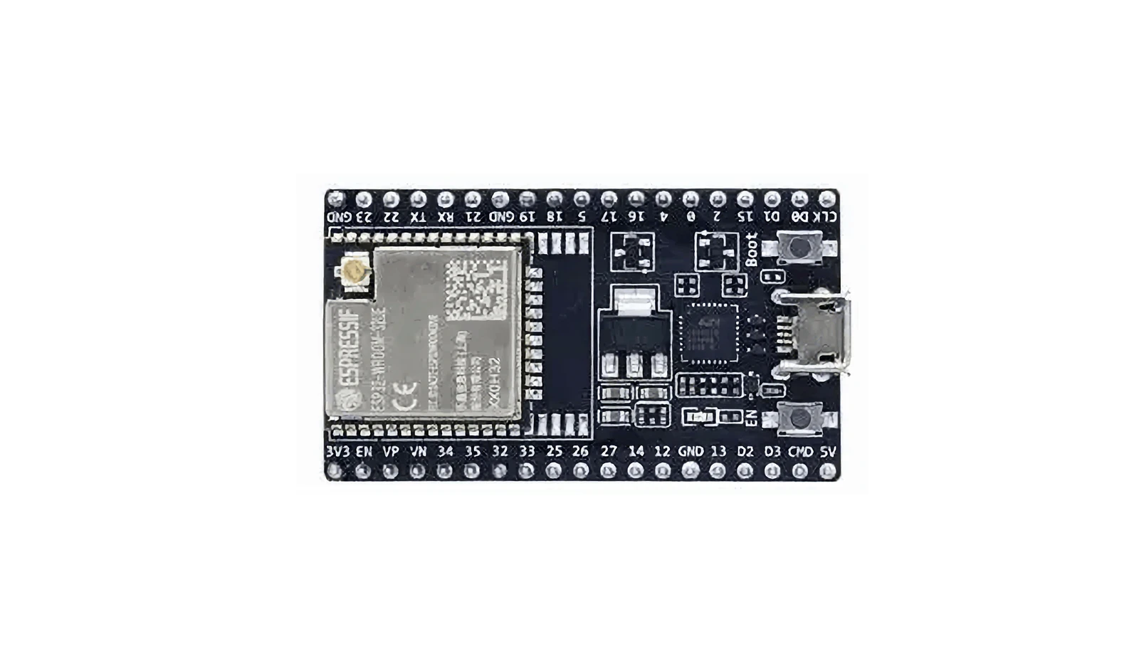
Purpose
Before diving into anything more ambitious, I needed to make sure the ESP32 board actually worked — that I could flash it, talk to it over USB, and see output from a running program. It’s the kind of sanity check that saves you hours of debugging later. If serial communication isn’t working, nothing downstream will either.
Code
void setup() {
  Serial.begin(115200);
}

void loop() {
  Serial.println("ESP32 OK");
  delay(1000);
}
Nothing fancy here — just initialising the serial port at 115200 baud and printing a heartbeat every second. If this shows up in the Serial Monitor, I know the board is alive, the USB-to-UART bridge works, and the Arduino IDE can talk to it properly.
Test Steps
- Select the ESP32 board and corresponding COM port in Arduino IDE.
- Connect the ESP32 via USB and upload the code.
- When
Connecting......appears, press the IO0 button on the ESP32 to enter flash mode. - After uploading, open the Serial Monitor and set the baud rate to 115200.
The IO0 button step caught me the first time — the ESP32 won’t enter flash mode automatically on every board, so you have to hold or tap IO0 when the IDE says “Connecting.” If you miss the window, the upload just times out and you try again. Classic ESP32 quirk.
Result
The Serial Monitor continuously outputs:
ESP32 OK
ESP32 OK
ESP32 OK
Everything checks out. The board takes a sketch, the sketch runs, and I can see the output. On to the next thing.